 |
|||
|
|
|||
|
Page Title:
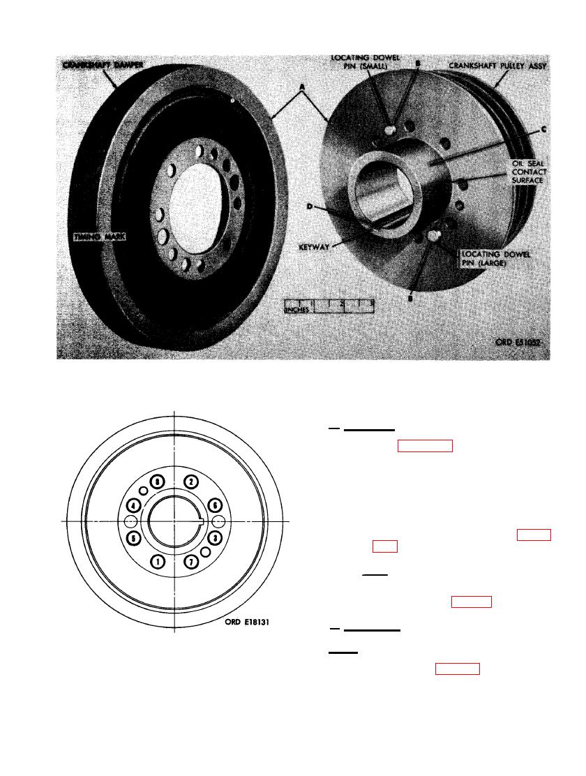
FIGURE 205. DISASSEMBLING, ASSEMBLING, AND INSPECTING CRANKSHAFT DAMPER AND PULLEY ASSEMBLY. |
|
||
| ||||||||||
|
|
 SHAFT DAMPER AND PULLEY ASSEMBLY.
d. Assembly.
(1) Refer to figures 204 and 205 and reverse
the sequence of illustrations and in-
structions to assemble the crankshaft
damper and pulley assembly.
(2) Tighten the eight cap screws securing
the crankshaft damper to the pulley
assembly to a torque of 300 pound inches
following the sequence shown in fig-
ure 206.
Note. After once torquing the cap
screws to 300 pound inches, they again
must be retorqued to 360 pound inches
in proper sequence (fig. 206).
e. Installation.
Note. Before installing crankshaft damper
and pulley assembly on crankshaft, coat lip of
crankshaft front oil seal (fig. 207) and sealing
surface on pulley with lubricating oil to prevent
CRANKSHAFT DAMPER AND PULLEY
damage to oil seal lip when pulley is. installed.
ASSEMBLY ATTACHING SCREWS.
135
|
|
Privacy Statement - Press Release - Copyright Information. - Contact Us |
