 |
|||
|
|
|||
|
Page Title:
VALVE ROCKER ARM SHAFTS AND/OR ROCKER ARM ASSEMBLIES |
|
||
| ||||||||||
|
|
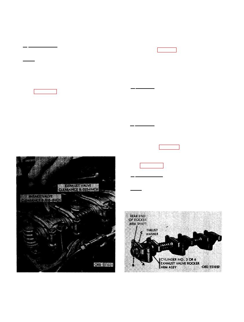 (C) Adjust remaining valves in same
adjusting screws. Do not tighten valve rocker
manner. The intake valve is the front
arm adjusting screw lock nuts until valve clear-
valve and exhaust valve is the rear
ance has been adjusted.
valve.
d. Adjustment. Adjust valve clearance as
(2) Refer to figure 62 and reverse the se-
follows.
quence of instructions to install the front
cylinder head cover. Use a new cover
Note. Before adjusting valve clearance, ro-
gasket and breather adapter gasket.
tate crankshaft as necessary to bring tappets
on base circle of camshaft for valve being
adjusted. Determine position of tappets by
observing the up and down movement of the
ROCKER ARM ASSEMBLIES
push rod as the crankshaft is rotated.
a. General. The front and rear set of valve
roc-ker arm shafts and rocker arm assemblies
(1) Figure 183. (A) Turn intake valve rocker
arm adjusting screw as necessary to
are replaced in the same manner. For in-
obtain a clearance of 0.015- inch. Tighten
structional purposes, the front set of valve
valve rocker arm adjusting screw lock
rocker arms will be removed for replacement
nut after proper clearance is obtained,
of rocker arm shaft or rocker arm assemblies
holding adjusting screw stationary while
and for repair of the rocker arm assemblies.
tightening lock nut. (B) Turn exhaust
valve rocker arm adjusting screw as
b. Removal. Remove rocker arm assemblies
necessary to obtain a clearance of 0.025-
as follows.
inch. Tighten valve rocker arm adjust-
ing screw lock nut after proper clear-
(1) Remove front cylinder head cover and
ance is obtained, holding adjusting screw
gasket following instructions which ac-
stationary while tightening lock nut.
company figure 62.
(2) Remove front set of rocker arms fol-
lowing instructions which accompany
c. Disassembly. Disassemble rocker arm
assembly as follows.
Note. Cylinder No. 3 (or No. 6) exhaust valve
rocker arm assembly must be removed from
the rear end of rocker arm shaft, due to a locat-
ing dowel pin.
CYLINDER NO. 3 (OR 6) EXHAUST
EXHAUST VALVE CLEARANCE.
VALVE ROCKER ARM ASSEMBLY.
124
|
|
Privacy Statement - Press Release - Copyright Information. - Contact Us |
