 |
|||
|
|
|||
|
Page Title:
FRONT AND/OR REAR CYLINDER HEAD WATER OUTLET MANIFOLDS |
|
||
| ||||||||||
|
|
 90. FRONT AND/OR REAR CYLINDER HEAD
(3) Figure 177. (A) Remove and discard
WATER OUTLET MANIFOLDS
intake manifold elbow gasket. (B) Re-
move water temperature sending unit.
a . General. For instructional purposes, the
(C) Remove 3/8-inch square head pipe
front cylinder head water outlet manifold will
plug. (D) Remove 1/2- inch square head
be removed and installed.
pipe plug. (E) Remove 1/4- inch square
head pipe plug.
b. Removal. Remove water outlet manifolds
as follows.
c . Assembly. Refer to figures 175 through
177 an reverse the sequence of illustrations
(1) Remove front cylinder head cover and
and instructions to assemble the intake mani-
gasket following instructions for fig-
fold assembly. Use a new intake manifold elbow
ure 62.
gasket. Replace the turbosupercharger -to - in-
take manifold hose when necessary.
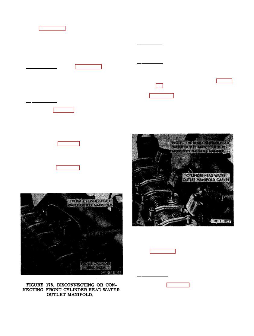
(2) Figure 178. (A) Loosen the two 1-5/8-
inch hose clamps securing cylinder
d. Installation.
head water outlet manifold-to- intake
manifold hose. (B) Remove six 5/16 x
(1) Refer to figures 168 through 172 and re-
2-1/4 cap screws and 5/16- inch lock
verse the sequence of illustrations and
washers securing front cylinder head
instructions to install the intake mani-
water outlet manifold to f rent cylinder
fold assembly. Install new intake, ex-
head.
haust, and cylinder head water outlet
manifold gaskets.
(2) Refer to figures 44 through 47 and 49
through 52 and reverse the sequence of
illustrations and instructions to install
the turbosupercharger assembly.
(3) Refer to figures 109 through 111 and re-
FRONT CYLINDER HEAD WATER OUT-
LET MANIFOLD.
(3) Figure 179. (A) Remove front cylinder
head water outlet manifold. (B) Remove
and discard three cylinder head water
outlet manifold gaskets.
c. Installation.
(1) Refer to figures 178 and 179 and reverse
the sequence of illustrations and in-
structions to install the front cylinder
|
|
Privacy Statement - Press Release - Copyright Information. - Contact Us |
