 |
|||
|
|
|||
|
Page Title:
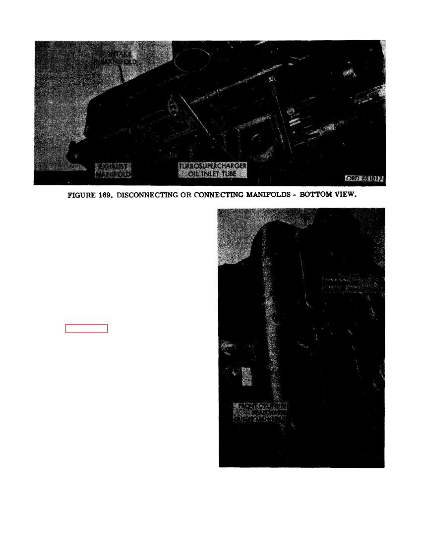
FIGURE 169. DISCONNECTING OR CONNECTING MANIFOLDS-BOTTOM VIEW |
|
||
| ||||||||||
|
|
 support from crankcase and bracket.
(D) Remove theoillevel gage rod sup-
port clamp bracket. (E) Remove six
5/16- inch plain nuts and 5/16-inch flat
washers securing bottom flanges of in-
take manifold to front and rear cylinder
heads.
(5) Figure 170. (A) Remove twelve 5/16
x 2-1/4 cap screws and 5/16-inch lock
washers securing front and rear cyl-
inder head water outlet manifolds to
front and rear cylinder head assemblies.
(B) Remove twelve 5/16-inch plain nuts
and 5/16- inch flat washers securing top
flanges of intake manifold to front and
rear cylinder head assemblies. (C) Re-
move six 7/16- inch self- locking nuts and
7/16-inch flat washers securing top
flanges of exhaust manifold to front and
rear cylinder head assemblies.
NECTING MANIFOLDS - TOP VIEW.
118
|
|
Privacy Statement - Press Release - Copyright Information. - Contact Us |
