 |
|||
|
|
|||
|
Page Title:
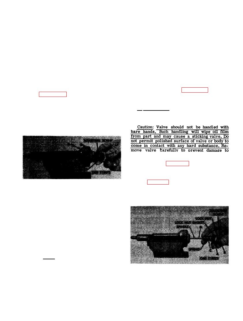
FIGURE 152. REMOVING OR INSTALLING NOZZLE AND HOLDER ASSEMBLY CAP |
|
||
| ||||||||||
|
|
 (4) Check nozzle spray pattern. Close the
d. Test Nozzle and Holder Assembly
gage valve and operate the pump handle
at approximately 15 strokes per minute.
(1) New nozzles should have an opening
pressure of 2750 to 2800 psi and used
If the two spray' holes are clean, the
nozzles should haveanopening pressure
spray pattern should be clean and sharp
with a uniform conical pattern of fuel
of 2500 plus or minus 25 psi to be con-
discharge. If the spray pattern is poor
sidered serviceable. Adjust nozzle
pressure by turning the adjusting screw
and does not improve with increased
clockwise to increase the opening pres-
operation, fuel impurities may have cor-
roded or eroded the spray holes and
sure and counterclockwise to decrease
the opening pressure. Refer to figure
the nozzle must be replaced. Properly
152 for instructions on removing nozzle
operating nozzles should not be dis-
and holder cap to gain access to the ad-
assembled and cleaned. Install locking
justing screw.
nut and cap by reversing sequence of
instructions for figure 152. Recheck
(2) Figure 152. (A) Clamp fuel injector
spray pattern after adjustment.
nozzle and holder assembly in a soft-
jawed vise. (B) Hold lock nut to prevent
turning adjusting screw when cap is
e. Disassembly. Disassemble nozzle and
removed. (C) Remove cap. Remove and
holder assembly as follows.
discard cap gasket.
.
.
surf aces.
(1) Refer to figure 152 and remove cap and
cap gasket from nozzle and holder as-
sembly.
(2) Figure 153. (A) Loosen locknut. (B) Re-
move adjusting screw and lock nut.
Remove and discard lock nut gasket.
(C) Remove spring. (D) Remove spindle.
NOZZLE AND HOLDER ASSEMBLY
CAP.
(3) Check nozzle leakage. With the pressure
valve open, actuate tester slowly to
build up pressure. As correct pressure
is approached, observe spray orifices.
If drops of fuel form or if fuel issues
as a stream below 2750 psi, the nozzle
is leaking and must be replaced.
Note. Normally a nozzle will chatter
or "bark" as it opens. This noise gen-
erally accompanies a properly func-
tioning nozzle and indicates that the
valve is free and that the seating sur-
LOCK NUT, ADJUSTING SCREW, SPRING,
face is good.
SPINDLE, AND GASKET.
109
|
|
Privacy Statement - Press Release - Copyright Information. - Contact Us |
