 |
|||
|
|
|||
|
Page Title:
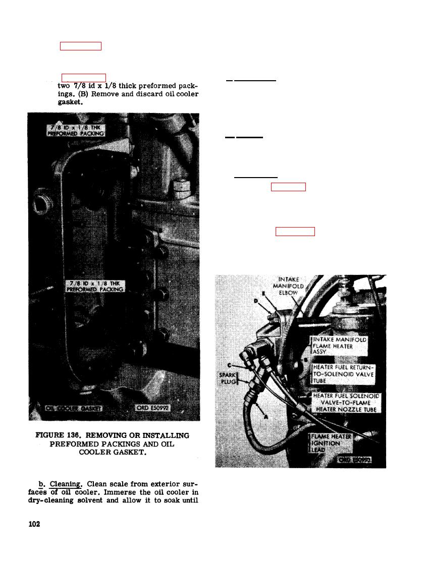
FIGURE 137. REMOVING OR INSTALLING INTAKE MANIFOLD FLAME HEATER ASSEMBLY. |
|
||
| ||||||||||
|
|
 oil passages are clean and unobstructed. Use
(5) Figure 135. (A) Remove and discard oil
probes, if necessary, to clean passages. Clean
cooler cover gasket. (B) Remove oil
cooler.
all gaskets and preformed packing areas.
(6) Figure 136. (A) Remove and discard
c. Inspection. Examine all gasket and pack-
ing-areas for damage. Plug one oil opening in
the oil cooler and apply 150 pounds per square
inch air pressure to the other opening. Immerse
the oil cooler in water and check for leaks. If
leaks are present, replace the oil cooler.
d. Repair. Repair minor damage to the gas-
ket and packing areas, such as nicks or burs,
with a fine mill file or crocus cloth. If any
other damage exists, replace the oil cooler.
--. Installation.
e
(1) Refer to figures 132 through 136 and re-
verse the sequence of illustrations and
instructions to install the oil cooler.
Use new preformed packings and gas-
kets.
(2) Refer to figures 103 and 104 and reverse
the sequence of illustrations and in-
structions to install the primary and
final fuel filters.
INTAKE MANIFOLD FLAME HEATER
ASSEMBLY.
|
|
Privacy Statement - Press Release - Copyright Information. - Contact Us |
