 |
|||
|
|
|||
|
|
|||
| ||||||||||
|
|
 ASSEMBLY.
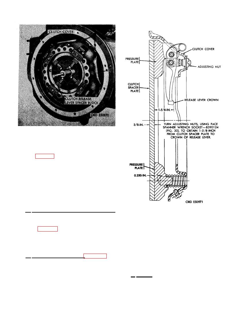
(2) Figure 97. (A) Position clutch cover as-
sembly over driven member assembly
and aline screw holes. (B) Secure cover
assembly to flywheel using eight 3/8
lock washers and 3/8 x 15/16 cap
screws. Tighten cap screws to a torque
of 275 to 325 pound inches. (C) Depress
clutch release levers, one at a time,
and remove four clutch release lever
spacer blocks. (D) Remove clutch aline-
ment tool.
d. Adjustment of Clutch Release Levers.
After clutch assembly is installed, adjust clutch
release levers to 1-5/8 inch from surface of
clutch spacer plate to release lever' crown as
shown in figure 98.
LEASE LEVER.
scratches, wear, or obstructions. Clean bore
a. Removal and Inspection. Figure 99. (A)
thoroughly using dry- cleaning solvent or mineral
Remove oil filter bypass valve plug and plain
spirits paint thinner. Remove slight burs and
washer from oil cooler and filter housing. Dis-
scratches in bore with crocus cloth.
card plain washer. (B) Remove oil filter bypass
spring and plunger from machined bore in oil
b. Repair. Repair of the oil filter bypass
cooler and filter housing. (C) Inspect oil filter
valve components is limited to replacement of
bypass valve plunger bore in housing for burs,
parts.
86
|
|
Privacy Statement - Press Release - Copyright Information. - Contact Us |
