 |
|||
|
|
|||
|
Page Title:
FIGURE 82. REMOVING OR INSTALLING AIR COMPRESSOR DRIVE BELT. |
|
||
| ||||||||||
|
|
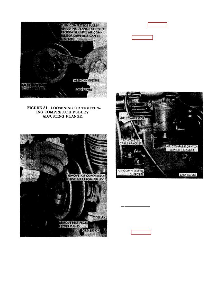 (3) Refer to figure 82 and remove the air
compressor drive belt.
(4) Figure 83. (A) Remove 1/4- inch cap
screw and clip holding fuel return-
to-fuel injection pump overflow valve
tube to air compressor. Install cap
screw on air compressor. (R) Remove
four 7/16- inch plain nuts and 7/16- inch
lock washers securing air compressor
assembly to air compressor support
assembly. Remove tachometer cable
bracket. (C) Remove air compressor
assembly. (D) Remove and discard air
compressor-to- support gasket.
AIR COMPRESSOR ASSEMBLY.
b. Disassembly. The air compressor assem-
bly-must be partially disassembled. Remove the
air compressor adjustable pulley, air intake
manifold, and air discharge housing from the
air compressor assembly as follows.
(1) Figure 84. (A) Remove air compressor
pulley adjusting flange from hub on
compressor pulley. (B) Remove 3/4-
inch self- locking nut securing pulley
to compressor shaft. (C) Remove air
compressor pulley using a suitable
AIR COMPRESSOR DRIVE BELT.
puller.
79
|
|
Privacy Statement - Press Release - Copyright Information. - Contact Us |
