 |
|||
|
|
|||
|
Page Title:
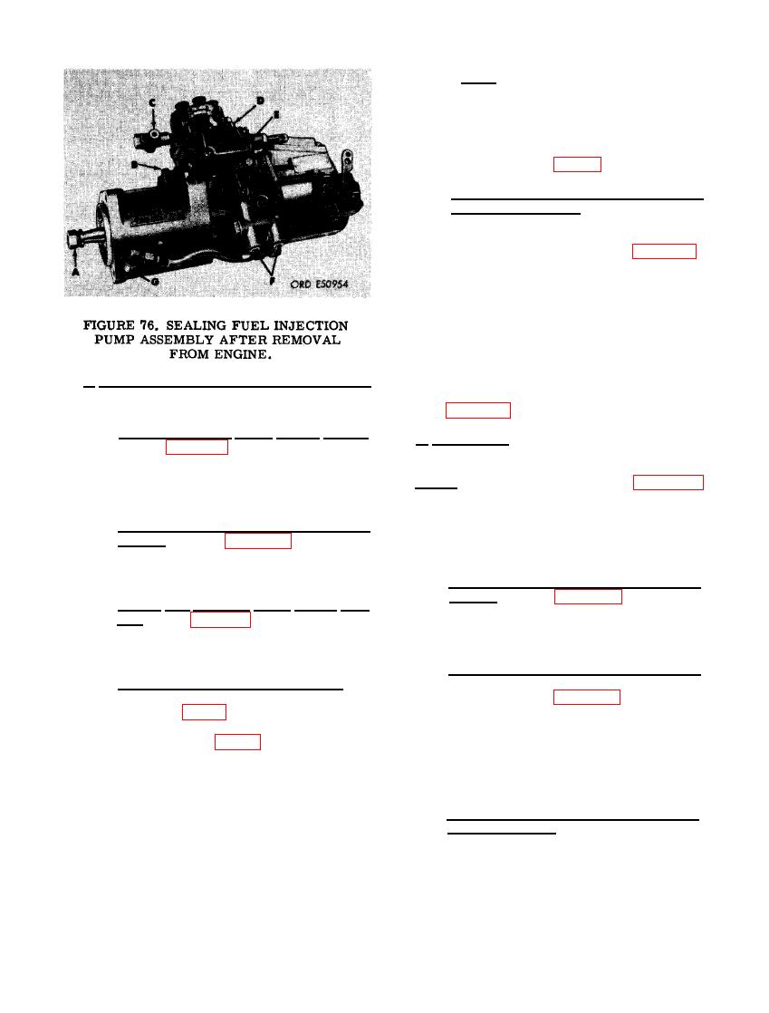
Preparation of Fuel Injection Pump for Installation |
|
||
| ||||||||||
|
|
 Note. The pump camshaft contains an
over-center lobe which tends toprevent
the timing mark on the hub from re-
maining in line with its mating pointer.
These marks must be alined when in-
stalling injection pump driven gear and
retaining plate (fig. 77).
(5) Check engine timing before installing
fuel injection pump. The engine timing
is correct when the mark on crankshaft
damper and pulley assembly is alined
with the point er as shown in figure 66,
and when No. 1 piston is on the com-
pression stroke. For convenience, the
engine timing marks were alined before
the pump was removed. When engine
timing marks are not alined, rotate the
engine clockwise as viewed from the
front until timing mark on damper and
pulley assembly is alined with pointer,
c. Preparation of Fuel Injection Pump for
and No. 1 piston is on compression
stroke as illustrated and instructed in
Installation. Prepare the fuel injection pump for
installation as described in (1) through (5) below.
(1) Remove injection pump timing covers.
d. Installation. Install fuel injection pump on
Refer to figure 76 and reverse the se-
engine as described in (1) through (7) below.
quence of instructions to remove timing
cover, timing window cover, dirt plugs
Note. Whenever connector "C" in figure 76
or caps, and automatic advance unit
is installed in the fuel injection pump, the pump
shaft lock washer and nut.
must be flushed to clean out any loose metal
which may result from installing the connector.
(2) Install fuel tube or hose elbows and con-
Failure to do so can result in major damage to
nector. Refer to figures 74 and 75 and
reverse the sequence of instructions to
the pump distributor head assembly.
install tube and hose elbows and con-
(1) Install fuel injection pump assembly on
nector.
engine. Refer to figures 64 through 71
(3) Install fuel injection pump driven gear
and reverse the sequence of illustra-
hub Refer to figures 72 and 73 and re-
tions and instructions to install fuel in-
verse the sequence of instructions to
jection pump assembly on engine.
install the fuel injection pump driven
gear hub.
(2) Install fuel injection pump driven gear
and time pump in relation to engine
(4) Time fuel injection pump assembly. The
timing. Refer to figures 66 and 67 and
timing mark on the "automatic advance
reverse the sequence of illustrations
unit hub (fig. 64) must be alined with
and instructions to install fuel injection
pointer when the marked tooth in the
timing window (fig. 65) is visible. It is
pump driven gear. Do not tighten the
three 3/8 x 1-1/4 cap screws securing
possible to have the timing marks in the
driven gear and driven gear retaining
advance unit alined and not have the
marked tooth on the plunger drive gear
plate at this time.
in the timing window visible. When the
marked tooth is visible and the advance
(3) Check fuel injector pump timingin re-
lation to engine timing Before com-
unit marks are alined, the pump is prop-
pleting fuel injection pump installation,
erly timed. If the marked tooth is not
check pump to engine timing. Rotate
visible, rotate the gear hub 360 degrees,
crankshaft 90 degrees from timing
in either direction so the timing marks
marks. Return crankshaft to timing
do aline. This insures proper timing
mark position and check alinement.
when the pump is installed on the engine.
76
|
|
Privacy Statement - Press Release - Copyright Information. - Contact Us |
