 |
|||
|
|
|||
|
Page Title:
FIGURE 74. REMOVING OR INSTALLING PUMP FITTINGS (LATE MODEL ENGINES) |
|
||
| ||||||||||
|
|
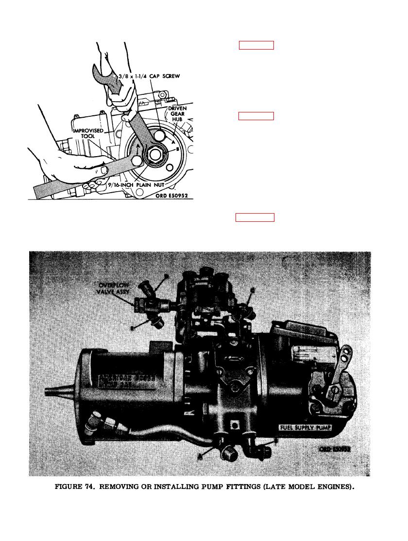 (20) Figure 73. (A) Install two 3/8 x 1- 1/4
cap screws through the holes in curved
portion of improvised tool and into two
tapped holes in driven gear hub. (B)
Remove 9/16- inch plain nut and lock
washer from shaft, holding driven gear
hub stationary with improvised tool
while turning nut.
(21) Figure 74. (A) Remove 3/8 tube x 1/4
pipe, 45 degree elbow from fuel inlet
port in fuel supply pump. (B) Remove
3/8 tube x 1/4 pipe, 90 degree elbow
from fuel outlet port in fuel supply
pump. (C) Remove 3/8 tube x 1/4 pipe,
45 degree elbow from fuel injection
pump assembly. (D) Remove 1/4 tube
x 1/8 pipe, 90 degree elbow from over-
flow valve assembly. (E) Remove 3/8
tube x 1/4 pipe, 45 degree elbow from
overflow valve assembly.
(22) Figure 75. (A) Wrap tape around fuel
injection pump automatic advance unit
shaft to prevent Woodruff key from
PLAIN NUT FROM FUEL INJECTION
PUMP ADVANCE UNIT SHAFT.
74
|
|
Privacy Statement - Press Release - Copyright Information. - Contact Us |
