 |
|||
|
|
|||
|
Page Title:
FIGURE 62. REMOVING OR INSTALLING FRONT CYLINDER HEAD COVER. |
|
||
| ||||||||||
|
|
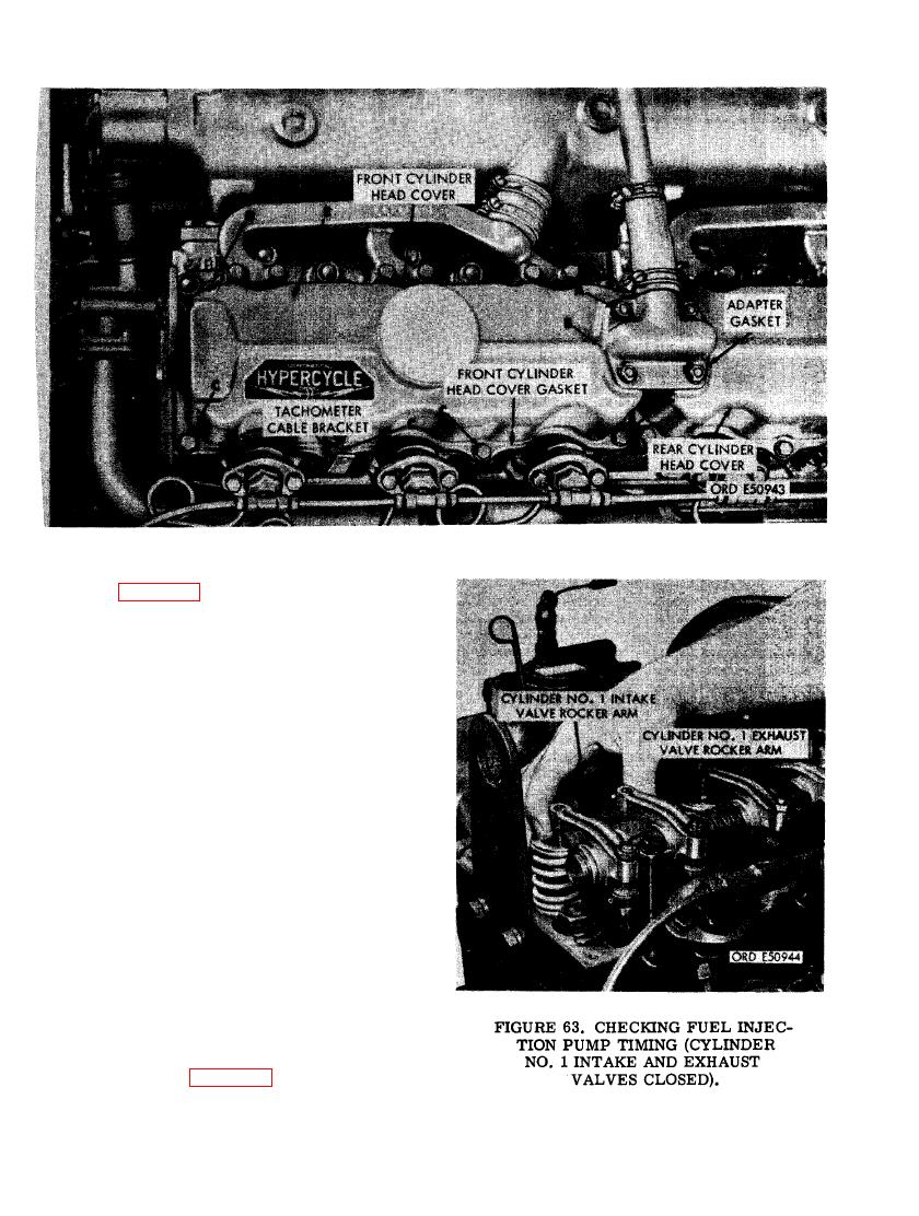 (8) Figure 62. (A) Remove four 5/16-inch
plain nuts and 5/16- inch lock washers
securing crankcase breather adapter
to the front and rear cylinder head
covers. (B) Lift breather adapter from
cylinder head covers and swing adapter
clear of studs in cylinder head covers.
Remove and discard two crankcase
breather adapter gaskets. (C) Remove
seven 5/16 x 7/8 cap screws and 5/16-
inch lock washers securing front cyl-
inder head cover to cylinder head. Re-
move tachometer cable bracket. (D)
Remove one 5/16-inch self-locking nut
from stud on right front corner of cyl-
inder head cover. Early model engines
cylinder head covers were secured with
a lock washer and a plain nut at the
right front corner. When installing cyl-
inder head cover cap screws and nuts,
torque tighten screws and nuts to 30-60
pound inches. (E) Remove front cylinder
head cover. Remove and discard cover
gasket.
(9) After removing front cylinder head
cover ((8) above) check position of cyl-
inder No. 1 intake or exhaust valves as
shown in figure 63. When both valves
70
|
|
Privacy Statement - Press Release - Copyright Information. - Contact Us |
