 |
|||
|
|
|||
|
Page Title:
FIGURE 59. DISCONNECTING OR CONNECTING FUEL HOSES FROM FUEL INJECTION PUMP (LATE MODEL ENGINES). |
|
||
| ||||||||||
|
|
 (3) Figure 58. (A) Remove two 1/4- inch
(5) Figure 60. (A) Plug fuel injection tube
self- locking nuts, 1/4- inch flat washers,
openings in injection pump hydraulic
and 1/4 x 1-3/8 cap screws securing
head and tubes to prevent entry of dirt.
outer clamp to inner clamp. Remove
(B) Disconnect swivel end of fuel sup-
outer clamp. (B) Disconnect cylinder
ply pump-to-fuel filter inlet hose from
No. 4, 5, and 6 fuel injection tube as-
3/8 tube x 1/4 pipe, 45 degree elbow at
semblies from fuel injection pump as-
bottom of fuel supply pump assembly.
sembly.
(C) Remove 1/4-inch plain nut, 1/4-
inch lock washer, and hose clamp at-
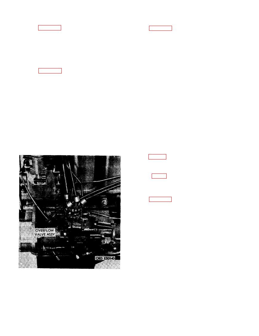
(4) Figure 59. (A) Plug fuel injection tube
taching fuel hoses to stud in the fuel
openings and tubes in fuel injection
injection pump bracket assembly. (D)
pump hydraulic head to prevent entry
Disconnect fuel injection overflow and
of dirt. (B) Disconnect fuel supply
fuel return-to- fuel filter inlet hose from
pump-to-fuel filter inlet hose from
3/8-inch tube tee in fuel filter assembly.
3/8 tube x 1/4 pipe, 90 degree elbow
Disconnect other end of hose from over-
at bottom of fuel supply pump assembly.
flow valve assembly in fuel injection
(C) Disconnect fuel injection overflow
pump assembly. Plug all openings to
and fuel return-to- fuel filter inlet hose
prevent entrance of dirt.
from 3/8 tube x 1/4 pipe, 45 degree
elbow in overflow valve assembly.
Note. When installing fuel return-to-
Note. When installing fuel return-to-
fuel filter inlet hose on overflow valve
fuel filter inlet hose on overflow valve
assembly, rotate valve slightly so as
assembly, rotate valve slightly so as
not to kink fuel return hose.
not to kink fuel return hose.
(6) Check timing of fuel injection pump
pump from engine. The crankshaft dam-
per and pulley assembly is marked at
27 degrees btdc (before top dead center)
(F, fig. 61) indicating correct fuel in-
jection pump timing, providing cylinder
No. 1 piston is on compression stroke.
(7) Figure 61. (A) Remove two 3/8-inch
plain nuts and 3/8- inch lock washers
and the 3/8 x 3-3/4 cap screws (B) Re-
move three 3/8- inch plain nuts and 3/8-
inch lock washers from studs. (C) Re-
move fuel injection pump drive gear
access cover and cover gasket. Discard
gasket. (D) Remove four 1/4 x 5/8 ma-
chine screws and 1/4- inch lock washers
securing timing cover to injection pump
automatic advance unit. Remove cover
and cover gasket. (E) Remove two 1/4
x 1- 1/4 fillister- head screws and 1/4-
inch lock washers securing timing
window cover to fuel injection pump as-
sembly. Remove cover. (F) Rotate
crankshaft clockwise, viewed from front
of engine, until mark (F) on crankshaft
damper and pulley assembly alines with
NECTING FUEL HOSES FROM FUEL IN-
pointer on gear cover.
JECTION PUMP (LATE MODEL ENGINES).
68
|
|
Privacy Statement - Press Release - Copyright Information. - Contact Us |
