 |
|||
|
|
|||
|
Page Title:
Figure 8-2. Engine connection points - left rear view. |
|
||
| ||||||||||
|
|
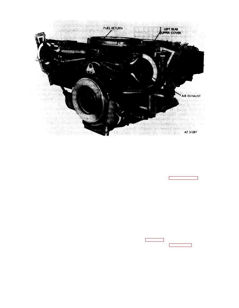 Figure 8-2. Engine connection points - left rear view.
c. Starting Procedures. D u r i n g c o l d w e a t h e r ,
(5) When engine oil pressure does not reach
when ambient temperature is below 30 degrees
t h e minimum 15 psi pressure within 20 seconds,
F, use engine manifold flame heaters to start
STOP THE ENGINE IMMEDIATELY b y
engine.
holding the fuel shutoff switch in the "OFF"
N o t e . Do not attempt an engine start until the
position. Determine the cause of low pressure.
fuel shutoff solenoid is connected and ascer-
Refer to troubleshooting, paragraph 3-9.
tained to be operative.
N o t e . After starting engine, run at idle, 675
to 725 rpm, for five minutes to permit the engine
C a u t i o n : Do not operate the starter motor
to warm up and to circulate the oil. Check oil
c o n t i n u o u s l y for more than one minute. Allow a
two-minute cool-off period before re-energizing
l e v e l and add sufficient oil to bring oil level to
t h e starter.
" F U L L " mark on oil level gage. Oil level must
be determined with engine idling. Check all
(1) Remove pipe plug (F, fig. 6 245 or 8-1),
p u r g e system and bleed the secondary fuel filter
i t e m s vital to safe engine operation, such as fuel
or water separator filter to remove trapped air.
lines, oil lines, oil pressure, throttle control,
Install pipe plug.
m o u n t i n g bolts, coupling, thermocouple harness,
(2) Crank the engine several revolutions
etc.
with the fuel shutoff switch in the "OFF"
d. Run-in Schedule. A n o v e r h a u l e d e n g i n e
position to make certain the engine is not
s h o u l d be started and tested in accordance with
hydrostatically locked and is otherwise free.
the schedule (table 8-1).
(3) Turn on the master switch.
(4) Start engine by operating electric
2
is
performance curve. A variation of
starting motor with throttle in idle position
acceptable.
(Refer to Caution, above.)
8-5
|
|
Privacy Statement - Press Release - Copyright Information. - Contact Us |
