 |
|||
|
|
|||
|
|
|||
| ||||||||||
|
|
 5 , 5-4, and 4-10.
N o t e . After installing time totalizing meter on
e n g i n e , the engine name plate must be stamped
w i t h an "X" after the engine serial number. This
will show engine has a time totalizing meter
i n s t a l l e d . The time totalizing meter must be set
b a c k to zero (para 6-70b) before being installed.
e . G e n e r a t o r a n d A s s o c i a t e d P a r t s . Refer to
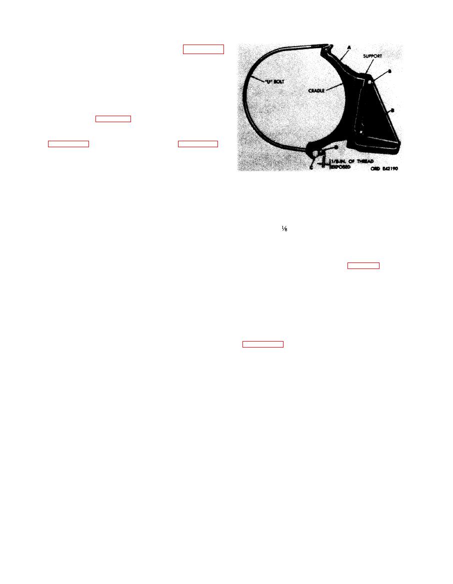
1. Position cradle (A) on generator support,
2. Install two self-locking nuts (B) and flat washers but do
not tighten.
3. Install clamping bar (C) on "U" bolt.
4. I n s t a l l self-locking nut (D). Tighten nut until ap-
-inch of bolt is exposed through the nut.
proximately
This is the approximate position of nut after "U" bolt
has been positioned over the generator, prior to in-
stalling the outside bar and nut.
generator part and must be in place before in-
stalling generator air intake tube.
Figure 7-35. Assembling generator cradle,
s u p p o r t , and "U'' bolt.
f. Test and Adjustments. After the egine has
it s h o u l d b e t e s t e d
been
completely
assembled
a n d the necessary adjustments made as directed
in Chapter 8 of this manual.
7-29
|
|
Privacy Statement - Press Release - Copyright Information. - Contact Us |
