 |
|||
|
|
|||
|
Page Title:
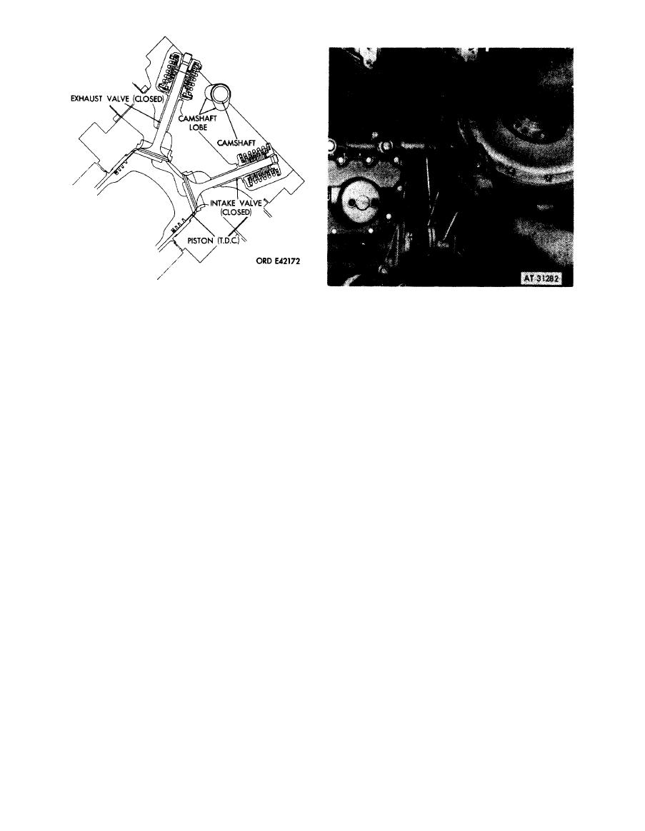
Figure 7-28. Correct position of camshaft lobes (cams) for fuel injection pump installation-sectional view. |
|
||
| ||||||||||
|
|
 1. Using two 5 / 16-in. steel rods (A), hold fuel injection
pump diaphragm pack stationary. Rotate flange
lobes (cams) for fuel injection pump
coupling counterclockwise to remove any backlash in
i n s t a l l a t i o n -sectional view.
injection pump gear train and bring the advance unit to
the full retard position.
2. When backlash is removed and timing marks alined,
install four lock washers and bolts (B) and tighten
securely.
Note. When installing bolts in diaphragm
coupling, be sure the proper length bolts - FSN
5306-944-7537 are used. Bolts longer than
53 / 64-inch can be threaded completely through
the coupling flange and dent the diaphragm
pack. This will create a high stress point and
possible
premature
coupling
failure.
7-29.
Removing
fuel
injection
pump
drive
gear
train
backlash
and
setting
advance unit retard position-
diaphragm coupling.
7-21
|
|
Privacy Statement - Press Release - Copyright Information. - Contact Us |
