 |
|||
|
|
|||
|
Page Title:
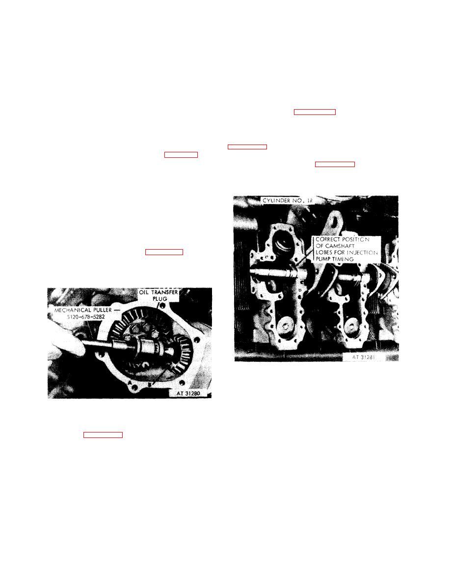
Figure 7-26. Installing right camshaft oil transfer plug |
|
||
| ||||||||||
|
|
 timing by rotating
(3) Check valve
(5) Rotate the crankshaft counterclockwise
crankshaft clockwise as viewed from rear, ap-
approximately 270 degrees from "6L INT
proximately 1 / 8 turn to remove gear backlash,
CLOSE .100 CLR" until flywheel timing mark
"6R INT CLOSE .100 CLR" is alined with
then turn counterclockwise until the valve is just
closed. Stop rotating the crankshaft the instant
timing pointer. Install the left camshaft and No.
the swivel pad becomes free. Observe position of
6L valve rocker cover following same procedure
flywheel timing mark. When timing mark on
as outlined for right camshaft and No. 6R valve
flywheel is alined within 1 / 8-inch of the timing
rocker cover.
pointer, the valve timing is correct. When timing
(6) Refer to figure 5-111 and install the
mark is not alined, withdraw camshaft drive
camshaft gear housing covers, using new
shaft, and repeat timing procedure ((2) above)
mounting
gaskets.
and again check valve timing. When correct
b. Fuel Injection Pump and Timing. Refer to
valve timing is obtained, install right oil transfer
plug following instructions in figure 7-26.
fuel injection pump. Torque tighten nut to 900
Note.
When correct timing cannot be
pound-inches. Refer to figures 4-71, 4-72, 4-65
obtained as described in (3), above, it may be
through 4-68, and 4-75 through 4-81. Additional
necessary to set timing mark 1 / 8 to 1 / 4-inch
pertinent
instructions
are
listed
below.
out of alinement before installing drive shaft.
(4) Set cylinder No. 6 intake valve clearance
by
rotating crankshaft counterclockwise ap-
proximately 1 / 4 turn in order to have No. 6R
intake valve rocker arm roller on base circle of
camshaft.
Set
intake
valve
clearance
to
final
0.010-inch setting, using thickness gage blade -
5120-793-7897 as shown in figure 7-22. Torque
tighten adjusting screw lock nut to 175 pound-
inches after adjustment.
7-27.
Correct
position
of
cylinder
1R
camshaft lobes (cams) for fuel injection
pump installation-installed view.
1. Install right oil transfer plug using mechanical puller-
5120-678-5282.
2. Refer to figure 5-112 and install retaining ring.
transfer plug.
7-20
|
|
Privacy Statement - Press Release - Copyright Information. - Contact Us |
