 |
|||
|
|
|||
|
Page Title:
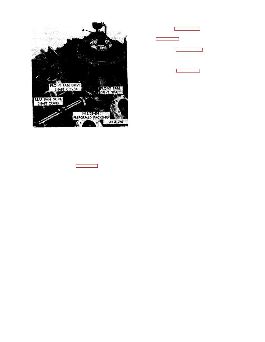
Figure 7-18. Installing front fan drive housing assembly using improvised lifting tool |
|
||
| ||||||||||
|
|
 (8) Refer to figure 5-123 and torque tighten
two drilled head cap screws to 275 pound-inches.
Refer to figure 5-121 and torque tighten seven
self-locking
nuts
to
275
pound-inches.
(9) Refer to figures 5-120 through 5-117
and install the fan horizontal drive shaft. Center
hose on drive shaft housing and tighten hose
clamps securely.
(10) Refer to figure 7-19 for the view of the
e n g i n e as it appears at this stage of assembly.
Note. To facilitate lifting the front fan drive
housing assembly, an improvised lifting tool
can be made from a piece of 3 / 8-in. dia bar
stock and a discarded slotted fan nut. Bend bar
stock to shape and securely weld ends of bar to
nut as illustrated in figure 2-1.
1. Install improvised lifting tool (A) on fan vertical drive
shaft.
2. Apply light coat of gasket cement (MIL-C-10523 Ord.)
on mounting base (B).
3. Lower front fan drive housing assembly and associated
parts on mounting base.
housing assembly using improvised
lifting tool.
7-14
|
|
Privacy Statement - Press Release - Copyright Information. - Contact Us |
