 |
|||
|
|
|||
|
Page Title:
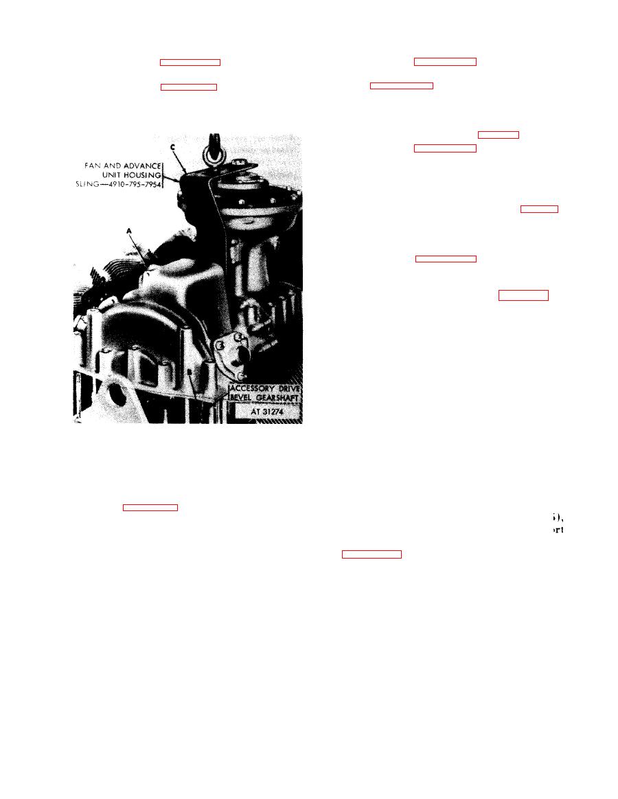
Figure 7-17. Installing rear fan and accessory drive housing using fan and advance unit housing sling-4910-795-7954. |
|
||
| ||||||||||
|
|
 (5) Refer to figure 5-130 and torque tighten
(3) Refer to figure 5-131 and install fan and
the 12 self-locking nuts (A) to 275 pound-inches.
advance unit housing sling - 4910-795-7954.
Refer to figure 5-129 and torque tighten 14 self-
(4) Refer to figure 7-17 and install rear fan
locking nuts to 275 pound-inches.
accessory drive housing with clutch
and
b.
Fuel
Injection
Pump
Mounting
Base.
assembly.
(1) Install new preformed packing on oil
transfer tube in crankcase (fig. 5-128).
(2) Refer to figure 5-127 and torque tighten
four bolts to 750 pound-inches.
Front Fan Drive Housing
with
Clutch
c.
Assembly and Mounting Base.
(1) Install new preformed packing at oil
transfer tube in crankcase assembly (fig. 5-126).
(2) Apply a thin coat of
gasket cement
(MIL-C-10523
Ord.)
on
the
mounting
base
lower mounting surface.
(3) Refer to figure 5-125 and torque tighten
ten
slotted nuts and two cap screws to 275
pound-inches.
(4) Position cover adapter (58, fig. B-26) on
front fan drive shaft cover (57). Similarly,
position adapter
(58)
on
rear
fan
drive
shaft
cover (62).
(5) Join the two shaft covers (58 and 621
using rubber hose (61) and two hose clamps
(60). Tighten hose clamps just enough to hold
the covers together as a unit. Install a preformed
packing (56) on adapter end of each shaft cover
(6) Install retaining ring (55) on front far
drive shaft (54).
Note. Do not install retaining ring in groove
located on the front spline. Ring must be located
1. Lower the rear fan and accessory drive housing assembly
(A) until holes in housing aline with studs in mounting
beyond the spline at this time.
base.
(7) Install front fan drive shaft with
2. Continue lowering housing until accessory drive bevel
retaining ring, in front fan drive bevel gearshaft
gearshaft gear teeth (B) engage with the gear teeth of
(50.1) of front fan drive housing and clutch
the accessory drive gear.
assembly. Long spline must enter gearshaft.
3. Refer to figure 5-131 and remove lifting sling (C) after
rear fan and accessory drive housing are positioned.
Install the assembled drive shaft covers
above) over the front fan drive shaft, with
housing toward front fan drive housing as shown
drive housing using fan and advance unit
in figure 7-18.
housing
sling-4910-795-7954.
7-13
|
|
Privacy Statement - Press Release - Copyright Information. - Contact Us |
