 |
|||
|
|
|||
|
Page Title:
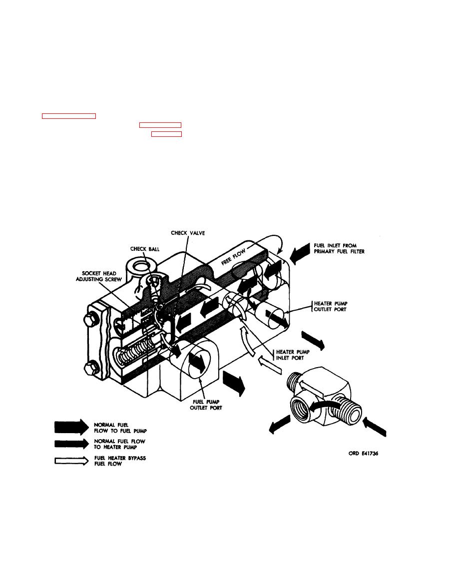
Figure 6-243. Fuel check valve flow diaphragm. |
|
||
| ||||||||||
|
|
 Note. Components of the fuel check valve are
not available as replacement parts. Therefore, no
further disassembly is required.
Figure 6-242. Deleted.
(2) Apply a pressure of 85 to 95 psi to the
b. Cleaning, Inspection and Repair. Refer to
heater pump inlet port. The check ball must
paragraphs 6-2, 6-3, and 6-4.
bypass fluid at this pressure. Adjust socket head
c. A s s e m b l y . R e f e r t o f i g u r e 6 - 2 4 1 .
adjusting screw (F, fig. 6-242) to obtain this
d. Test and Adjustment (fig.
opening pressure.
(1) Fill valve with test fluid, MIL-F-7024A
(3) Plug the fuel pump outlet port, and the
Type II, and apply a pressure of psi to port
"FREE FLOW" (fuel inlet from
heater pump outlet port, and apply a pressure of
marked
100 psi at heater pump inlet port. There should
primary fuel filter). The check valve must open
be no fuel leakage from the "FREE FLOW"
at this pressure. Valve operation can be deter-
port.
mined when
fluid
flows
from
the
fuel
pump
outlet port.
(4) If the valve fails to pass either test,
replace entire valve assembly.
6-204
|
|
Privacy Statement - Press Release - Copyright Information. - Contact Us |
