 |
|||
|
|
|||
|
Page Title:
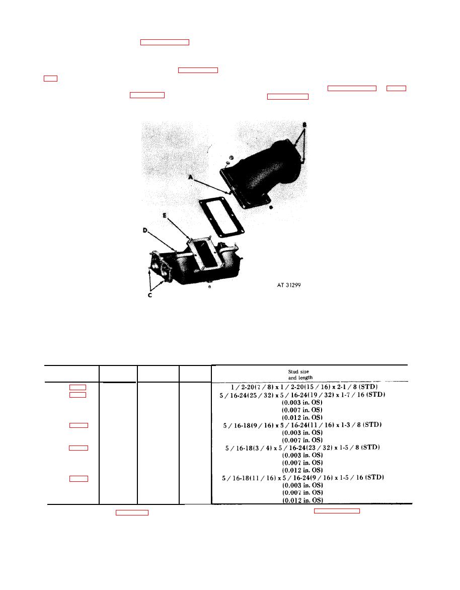
Figure 6-236. Right and left intake manifold-stud identification |
|
||
| ||||||||||
|
|
 threads or plugged
orifices.
Replace
damaged
heater assembly.
intake manifold rubber hoses using a dry cloth
only.
(2) Spark
plug. Refer
to
TM
9-8638
for
care and maintenance of spark plugs. Set plug
gap from 0.094 to 0.114 inches.
(3) Studs. Refer to paragraph 6-4e, table
(1) Manifold heater assembly. I n s p e c t
heater assembly (15, fig. B-21) for damaged
6-41, and figure 6-236 when replacing studs.
Right
and
left
intake
manifold-stud
identification.
Table 6-41. Manifold Heater Induction and Intake Manifold Standard
and Oversize Stud Identification
Ref.
Fig.
No.
Setting
No.
No.
req'd
height
1-3 / 8
4
9
13 / 16
15
8
D
13 / 16
16
A, E
12
1
B
25 / 32
12
C
23 / 32
24
228.
identification.
6-198
|
|
Privacy Statement - Press Release - Copyright Information. - Contact Us |
