 |
|||
|
|
|||
|
Page Title:
Section XII. OVERHAUL OF ENGINE SHROUDING ASSOCIATED PARTS |
|
||
| ||||||||||
|
|
 AND
SHROUDING
ENGINE
XII.
OVERHAUL
OF
Section
ASSOCIATED
PARTS
6-49. General
inspection, repair and assembly accompany the
overhaul operations. Refer to the following table
This
section
covers
the
overhaul
of
the
(table 6-39) for applicable illustrations
and
engine shrouding and associated components.
instructions for overhaul operations.
Specific instructions on disassembly, cleaning,
Table 6-39. Engine Shrouding and Associated Components
Component
Disassembly
Cleaning
Inspection
Assembly
Repair
Cooling Fan
Vanes
Engine and
Transmission
Shrouds
6-226
6-227
Oil Cooler
Frames,
Brackets, and
Associated
Parts
Cylinder Air
Deflectors
Overhaul of Engine Shrouding
and
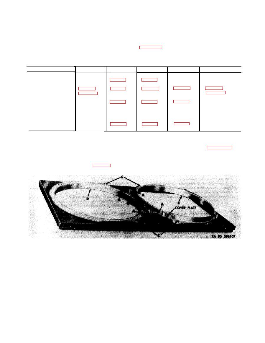
b. Disassembly. Disassemble cooling fan
Associated Components
housings, shroud rails, and cover plates following
instructions which accompany figures 6-226 and
a. General. Disassembly of the various shroud
6-227.
components other than the cooling fan housings,
shroud rails, and cover plates was accomplished
during engine disassembly, Chapter 5.
Remove
5. Remove rear cooling fan housing (E).
Install
Note. The four screws (A) and flat washers are
1. Position rear cooling fan housing (E) in cooling fan
an integral part of the cover plate and cannot be
shroud.
removed without destruction of flat washers.
2. Position front cooling fan housing (D) in shroud.
1. Loosen four screws (A).
3. Install four cap screws (C), lock washers, and flat
2. Remove two cap screws (B), self-locking nuts, and flat
washers.
washers.
4. Install two cap screws (B), self-locking nuts, and flat
3. Remove four cap screws (C), lock washers, and flat
washers.
washers.
5. Tighten four screws (A).
4. Remove front cooling fan housing (D).
6-191
|
|
Privacy Statement - Press Release - Copyright Information. - Contact Us |
