 |
|||
|
|
|||
|
|
|||
| ||||||||||
|
|
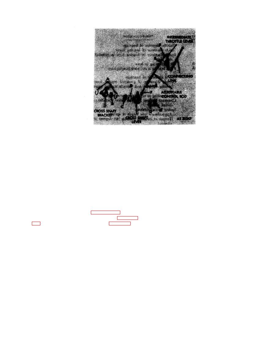 Assemble
Disassemble
1 . Install left and right rod end bearings (F) in ad-
1 . Remove two retaining rings (A) from cross shaft
justable control rod and tighten nuts (E).
bracket.
2. Install two retaining rings (D) in cross shaft lever.
2. Remove ball bearing (B) from brakcet.
3. Position two ball bearings (C) in lever.
3. Remove two ball bearings (C) from cross shaft lever.
4. Position ball bearing (B) in cross shaft bracket.
4. Remove two retaining rings (D) from lever.
5. Install two retaining rings (A) in bracket.
5. Loosen two nuts (E) and remove left and right rod end
bearings (F) from adjustable control rod.
not
to
be
disassembled.
Do
not
attempt
to
disassemble connecting link.
Disassembling
or
assembling
cross shaft lever, bracket, and
adjustable control rod.
b. Cleaning. Refer to paragraph 6-2.
c. Inspection and Repair. Refer
to
overhaul standards.
6-183
|
|
Privacy Statement - Press Release - Copyright Information. - Contact Us |
