 |
|||
|
|
|||
|
Page Title:
Figure 6-204. Installing fuel injection pump splined drive coupler half. |
|
||
| ||||||||||
|
|
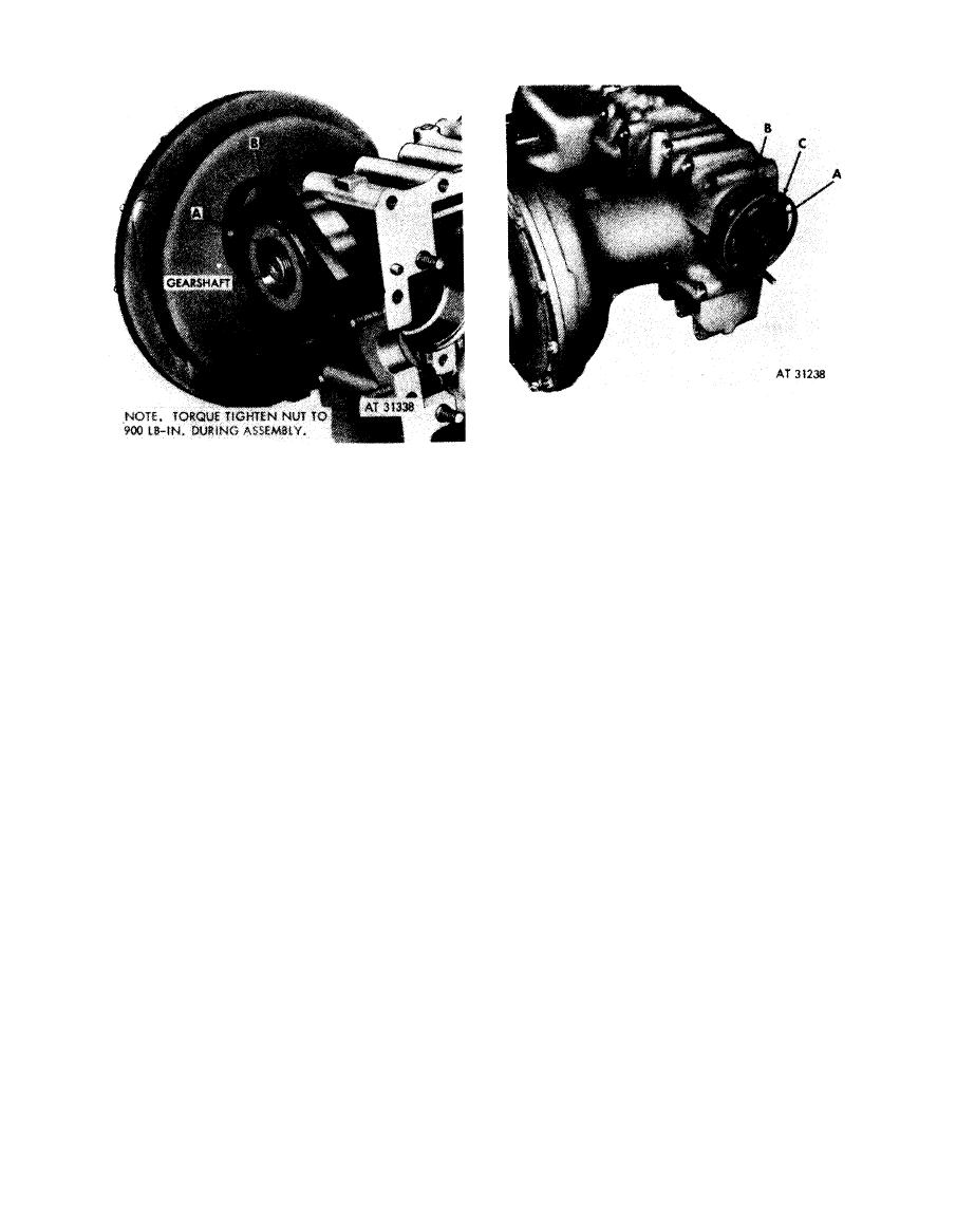 1. Position Woodruff key (A) in spur gearshaft.
2. Position pilot ring (B) on gearshaft.
Note. The
splined
coupler
halves
are
a
3. Position diaphragm coupler half (C) on gearshaft.
matched set. Make certain the coupler half being
installed matches the coupler half on the fuel
injection pump.
diaphragm
drive
coupler
half.
1. Position Woodruff key (A) in spur gearshaft.
2. Position coupler half (B) on spur gearshaft.
Figure 6-204. Installing fuel injection pump
splined drive coupler half.
6-172
|
|
Privacy Statement - Press Release - Copyright Information. - Contact Us |
