 |
|||
|
|
|||
|
Page Title:
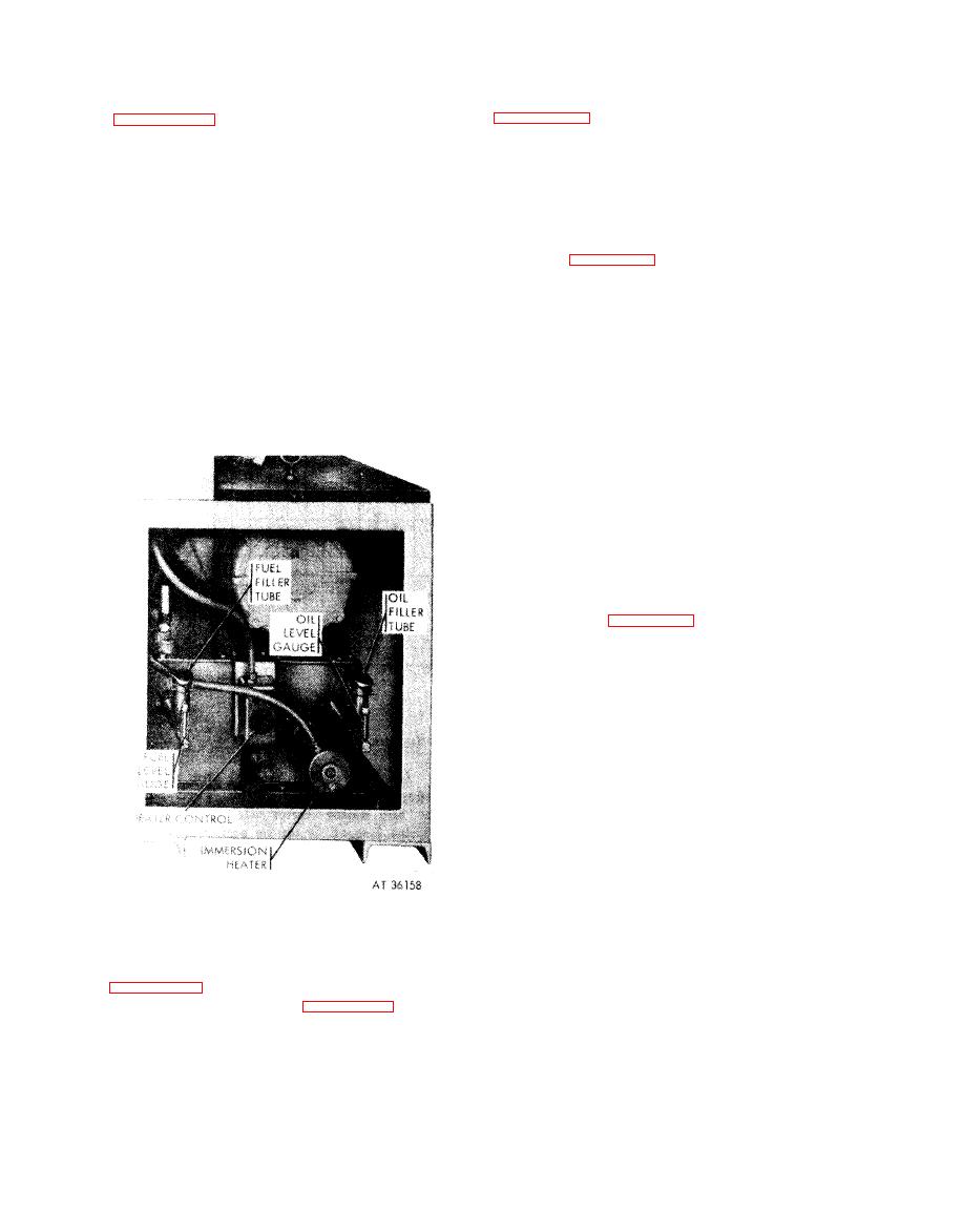
Figure 6-199c. Test stand heater control and supply tanks |
|
||
| ||||||||||
|
|
 (e) Turn the electronic counter switch,
(a) Check fuel level and oil level gages
figure 6-199b, "ON". The electronic com-
indicates less than half full (use oil, specification
ponents in the counter will reach operating
temperature by the time the test is begun.
MIL-L-45199 (Grade 30) or fuel, specification
VV-L-800).
(f) Loosen fasteners and remove fuel
(b)
Check
to
insure
that
the
master
injection pump drive housing cover from top of
switch, the oil heater switch, the jog run (clutch
test stand. Remove the two bearing caps and
engage) switch, and the motor switch are all in
intermediate bearing support
from
the
mounting
the "OFF" position and that the speed regulator
fixture, figure 6-201.
control is at zero (0).
(g) Install retaining ring on oil retaining
(c) Turn master
switch
handle
to
the
shaft. Install short (stub) end of oil retaining
"ON" position. Note that power indicator light
shaft
in
driven
(small)
end
of
the
advance
comes on. If power indicator light does not light,
assembly.
Install
support
over
bearing
on
large
press the reset buttons. If light still does not
gear end of advance assembly and install ad-
operate, investigate and correct the deficiency
vance assembly in bearing supports of mounting
before starting.
fixture
and
secure
with
hardware
removed
above. Install drive housing cover and secure
with fasteners.
Caution: The fuel injector pump advance
assembly drive housing cover must always be
installed and secured before operating test stand.
(h) Push jog run (clutch engage) switch to
engage eddy current clutch and turn speed
regulator control to obtain advance assembly
speed of 300 rpm on tachometer. Turn speed
regulator
control
clockwise
to
increase
rpm.
(i) Observe oil and fuel pressure in-
dicator gages, figure 6-199b. These gages should
register more than zero (0); however, maximum
pressures will not be evident until a speed of
2000 rpm is obtained.
Caution: Turn
master
switch
handle
"OFF" if there is no indication of oil or fuel
pressure on the gages. Investigate and correct the
deficiency before starting the test.
(j) Operate test stand at 300 rpm until the
oil temperature dial thermometer (H) stabilizes
at 250 degrees. It may require several minutes to
warm
the
entire
system
to
operating
tem-
perature. Note and record electronic counter (K)
reading (illuminated decimal digits on the front
of
the
counter
panel).
(k) Press oil drain push switch, located
Figure 6-199c. Test stand heater control and
immediately
below
the
oil
pressure
indicator
supply
tanks.
gage. The gage should register zero (0) psi with
the switch depressed. observe the counter
(d) Turn oil heater (thermostat) control,
reading. If the counter has changed more than
one (1) degree, the advance assembly requires
turn oil heater switch, figure 6-199b "ON". The
adjustment.
oil
heater
indicator
lamp
will
light
when
the
(1)
Release oil pressure drain
switch.
heater switch is turned on and will go out when
Turn
speed
regulator
control
clockwise
to
in-
the oil has reached the selected oil temperature
crease the speed to 600 rpm. Note and record the
heater
control
setting
(250
degrees).
6-167
|
|
Privacy Statement - Press Release - Copyright Information. - Contact Us |
