 |
|||
|
|
|||
|
Page Title:
Figure 6-68. Removing or installing oil pump pressure relief valve. |
|
||
| ||||||||||
|
|
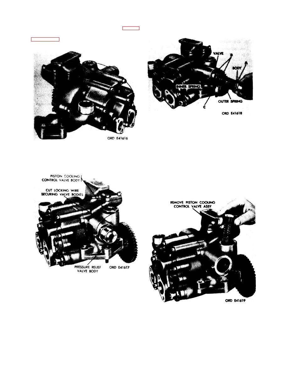 66) following instructions which accompany
Remove
1. Remove oil pump pressure relief valve body (A).
2. Separate pressure relief valve (B), outer valve spring.
and inner valve spring from valve body.
3. Remove cap screw (C) and flat washer.
Install
1. Install cap screw (C) and flat washer.
F i g u r e 6-66. FSN 2 8 1 5 - 8 9 5 - 6 4 3 0 oil pump
2. Position inner valve spring, outer valve spring, and
assembly as removed from engine.
pressure relief valve (B) in oil pump pressure relief
valve body (A).
3. Install assembled valve body (A) in pump housing.
Figure 6-68. Removing or installing oil pump
pressure relief valve.
wire securing oil pump pressure relief
valve and piston cooling control valve bodies.
Figure 6-69. Removing or installing piston
cooling control valve.
6-76
|
|
Privacy Statement - Press Release - Copyright Information. - Contact Us |
