 |
|||
|
|
|||
|
|
|||
| ||||||||||
|
|
 faces. Discard valves having badly pitted,
scored, scratched stems or locking grooves.
(b) Reface slightly pitted or burned
valves that do not seat perfectly to limits
specified in figure 6-63. Discard valves that
cannot be refaced to these limits.
( c ) Check valve length from seat contact
to tip of stem after grinding, as shown in figure 6-
6 3 . Discard valve if length is not within limits
specified (fig. 6-63).
(2) V a l v e s p r i n g s . R e p l a c e s p r i n g s ( 1 6 , 1 7 ,
and 18) when worn, cracked, or otherwise
d a m aged. Replace springs that do not conform
t o limits specified in overhaul standards (table 6-
15).
(3) Valve spring retainers, valve rotors, and
(a) Replace upper intake and exhaust
valve spring retainers (19 and 38) and valve
spring seat (15) when cracked or worn.
( b ) Replace valve rotors (40) when inner
section does not rotate freely or when assembly is
worn or cracked.
(c) Replace valve locks (20) when worn
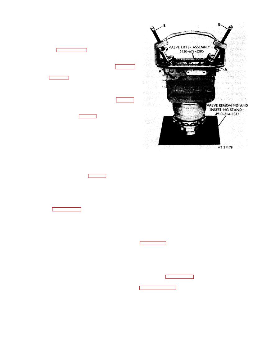
1. Position the valve lifter assembly - 5120-678-5285
or cracked.
over the valve springs and retainers (A) and secure in
6 - 3 4 . Assembly
position with four 5 / 16 x 1-3/8 bolts and 5 / 16-in.
flat washers.
2. Compress valve springs and retainers with screws (B)
(1) Install intake valve (12) and exhaust
and install two valve locks (20) in the groove of each
v a l v e (11) in their respective guides in cylinder
valve stem. Release valve spring compression. Remove
(41). Hold valves in position and place the
valve lifter assembly - 5120-678-5285 from cylinder
c y l i n d e r on valve removing and inserting stand -
and remove cylinder from stand.
4910-554-1317 following instructions which
accompany figure 6-65.
using valve lifter assembly-5120-678-5285.
(2) Install the exhaust valve rotor (40),
outer, intermediate, and inner springs (16, 17,
a n d 18), and upper exhaust valve spring retainer
(38) over the exhaust valve stem as shown in
seat (15), outer, intermediate, and inner springs
( 1 6 , 17, and 18), and upper intake valve spring
retainer (19) over the intake valve stem in the
same manner. Compress valve springs and
install valve locks following instructions which
accompany figure 6-65.
b. Valve Rocker Arm Covers. Refer to
6-74
|
|
Privacy Statement - Press Release - Copyright Information. - Contact Us |
