 |
|||
|
|
|||
|
Page Title:
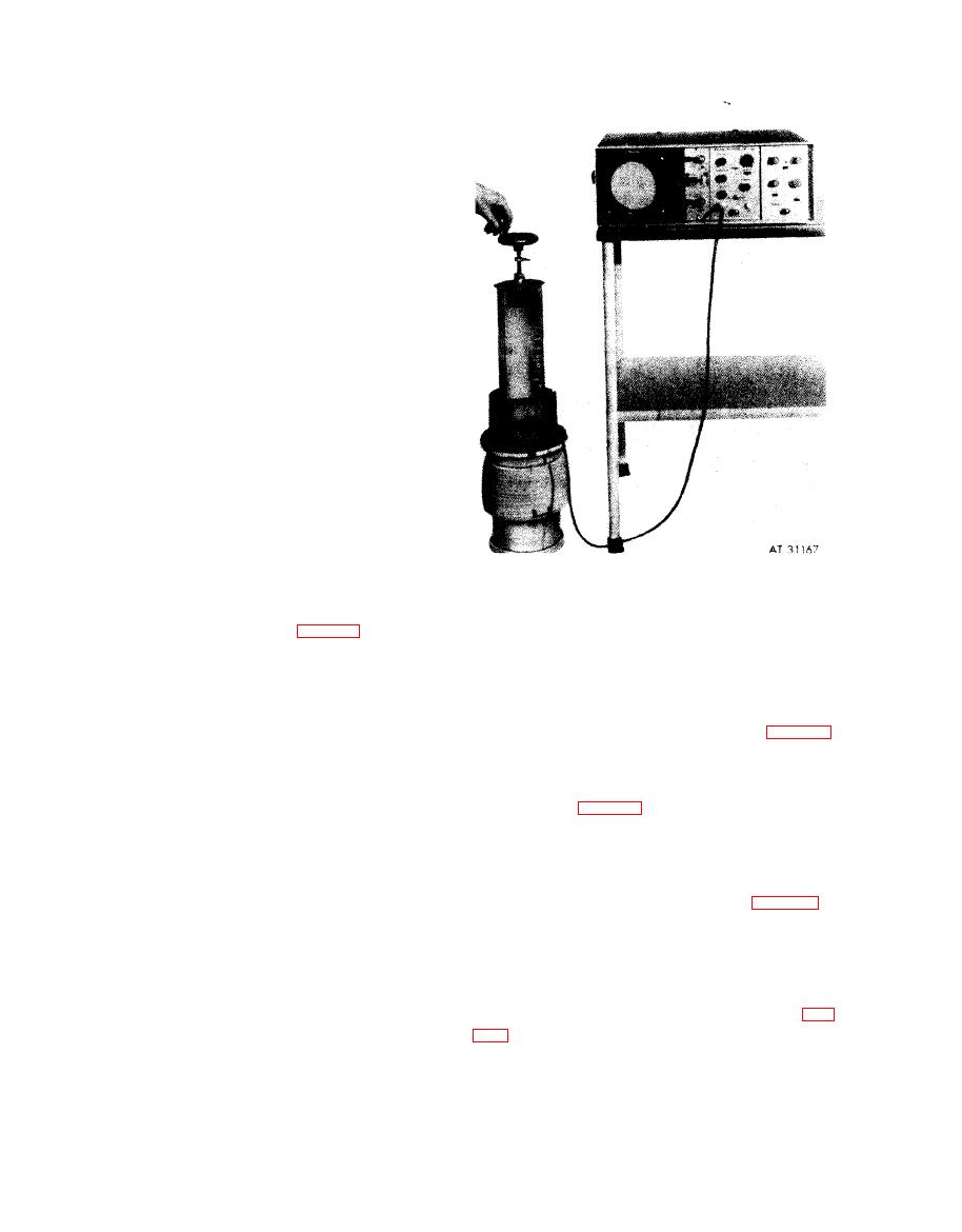
Figure 6-54. Ultrasonic search fixture installed on master checking cylinder. |
|
||
| ||||||||||
|
|
 (4) A d j u s t t h e I N T E N S I T Y s c r e w
c l o c k w i s e to brighten the wave form, but not to
the point where a bright spot occurs at the
beginning of the wave form.
C a u t i o n : Too much intensity can
damage display screen phosphor coating.
(5) Adjust the ASTIG screw to the
sharpest wave form.
(6) Adjust the FOCUS screw to the
sharpest wave form.
(3) Adjust the reflectoscope using the
master checking gage.
(a) Pour water into the master checking
gage, part No. 10935515, to the "FILL" level
( f i v e inches from top). Place the marked defect
portion of the gage facing the operator.
N o t e . Fresh water should not be used for
t e s t . Allow the water to stand twenty-four hours
before use. Add approximately one fluid ounce of
a n t i - c o a l e s c e n t agent, such as "Jet Dry", to each
ten gallons (37.85 liters) of water. The water,
master gage, and test cylinders should be at room
temperature during test.
Note. Wipe all air bubbles from the
c y l i n d e r wall. Bubbles may cause a false alarm
signal.
Figure 6-54. Ultrasonic search fixture
(b) Remove the protector from search
installed on master checking cylinder.
fixture probe. Place the search fixture on the
master checking gage (fig. 6-54), with the
(c) Connect the cable to the search fix-
UPPER-LOWER switch facing the operator.
t u r e , and to the reflectoscope at connector "R".
Place t h e s e a r c h f i x t u r e U P P E R - L O W E R
(d) Rotate the search fixture handle
switch to "UPPER".
counterclockwise to move the probe to the
uppermost position. The wave form on the
display screen will be similar to view B, fig. 6-53.
(e) Rotate the search fixture handle
clockwise to move the probe downward. Rotate
t h e search fixture handle until the echo pulse, or
spike (view C, fig. 6-53), is shown on the display
screen when the fixture pointer alines with the
master checking gage defect.
( f ) Move the search fixture probe upward
and downward until a maximum pulse is ob-
t a i n e d on the display screen (view C, fig. 6-53).
(g) Adjust the PULSE TUNING knob
(on pulser / receiver unit) to obtain the
maximum pulse height on the display screen.
(h) Adjust the SENSITIVITY control
knob (on pulser / receiver unit) to provide an
echo pulse height of 2-1 / 2 inches (view C, fig.
(i) Place the search fixture UPPER-
LOWER switch to "LOWER".
6-63
|
|
Privacy Statement - Press Release - Copyright Information. - Contact Us |
