 |
|||
|
|
|||
|
Page Title:
Figure 5-161. Preparing flywheel for removal. |
|
||
| ||||||||||
|
|
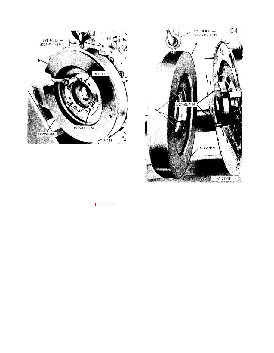 Note. Position flywheel to locate eye bolt hole
a t top center.
1. Install three 9 / 16 x 1-3/4 in. bolts (A), used for
attaching transmission drive gearshaft assembly, as
puller screws into puller screw holes in flywheel
2. Alternately tighten bolts and pull flywheel (B) from
crankshaft dowel pins only far enough to permit in-
C a u t i o n : Use care in removing the flywheel
stallation of lifting eye bolt (C).
from the dowel pins so as not to bind the flywheel
3. Install eye bolt - 5306-017-6143 and attach suitable
chain hoist. Continue tightening puller bolts to remove
on the pins.
flywheel from crankshaft dowel pins (fig. 5-162).
1. Remove flywheel (A) from the two dowel pins in
Figure 5-161. Preparing flywheel for removal.
flange on crankshaft.
2. Remove three puller bolts (B) from flywheel.
Figure.5-162. Removing flywheel using
e y e bolt-5306-017-6143.
5-92
|
|
Privacy Statement - Press Release - Copyright Information. - Contact Us |
