 |
|||
|
|
|||
|
Page Title:
Figure 5-141. Disconnecting or connecting cylinder deflectors at cylinders. |
|
||
| ||||||||||
|
|
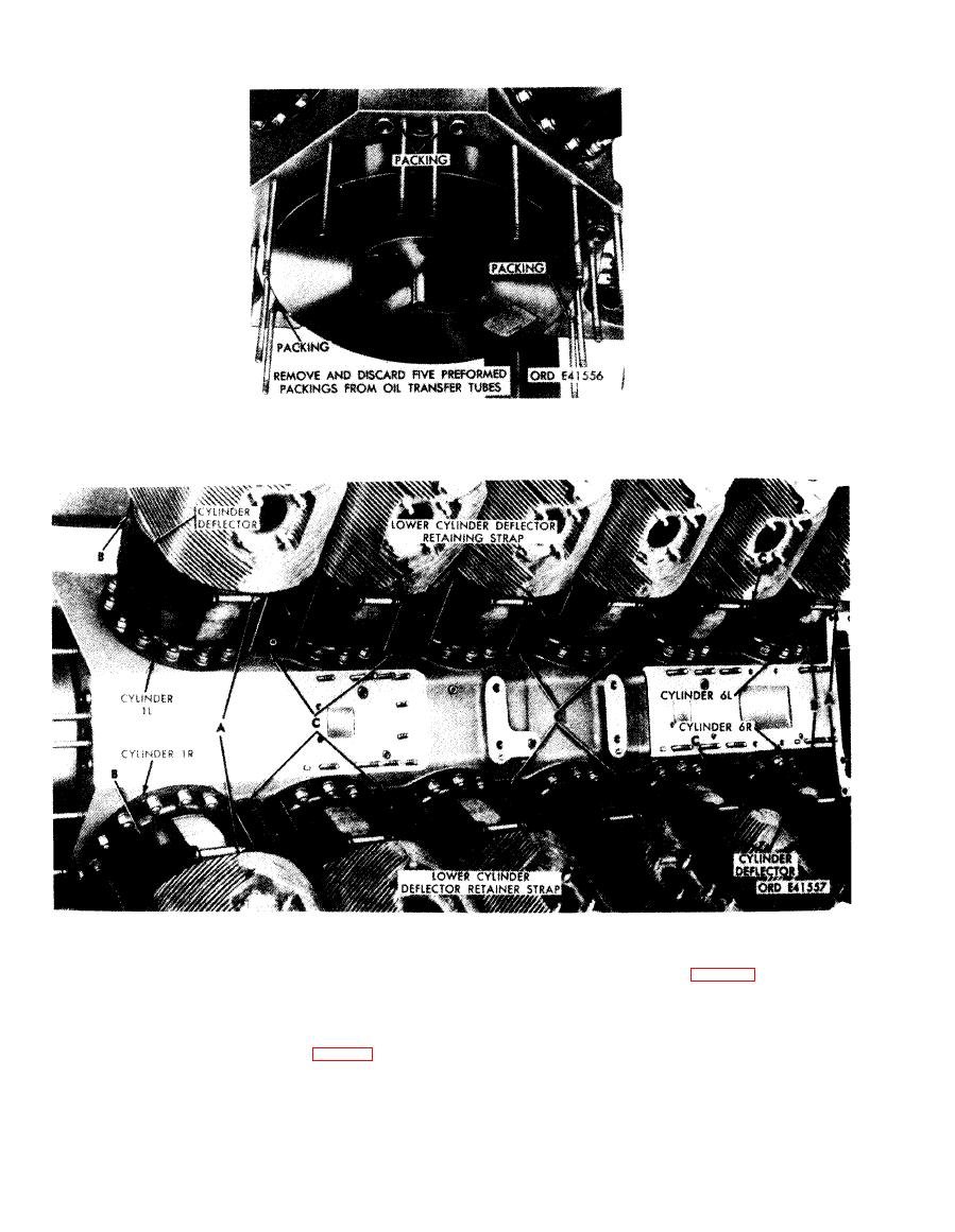 of oil transfer tube preformed packings.
Disconnect
Connect
1. Remove 12 self-locking nuts (A), cap screws, and
1. The ten cylinder deflector retainer straps (C) are
spacers attaching cylinder air deflectors around
secured by ten bolts. Install bolts (fig. 5-142).
cylinder assemblies.
2. Position the four air deflectors (B) located at cylinder
2. Remove the four air deflectors (B) located at cylinder
Nos. lR, lL, 6R, and 6L.
Nos. lR, lL, 6R, and 6L.
3. Install 12 self-locking nuts (A), cap screws, and
spacers securing cylinder air deflectors around cylinder
3. The ten lower cylinder deflector retainer straps (C)
assemblies.
are secured by ten bolts. Remove bolts ( fig. 5-142).
Figure 5-141. Disconnecting or connecting cylinder deflectors at cylinders.
5-78
|
|
Privacy Statement - Press Release - Copyright Information. - Contact Us |
