 |
|||
|
|
|||
|
Page Title:
Figure 5-105. Location of valve rocker arm cover and cylinder identifying marks |
|
||
| ||||||||||
|
|
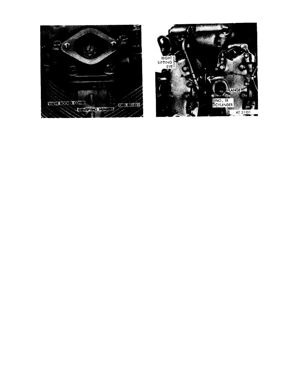 Disconnect
1. Remove three cap screws (A) attaching right lifting
eye to rocker arm cover and cylinder No. 1R.
N o t e . The cylinder and valve rocker arm
2. Remove three cap screws (B) attaching each in-
covers are machined as an assembly. Each
tercylinder hose flange to remaining covers and
rocker arm cover must be kept with its mating
cylinders on right side of engine. Slide flanges and
cylinder to insure camshaft bearing alinement
lifting eye away from rocker arm covers and cylinders.
Con nect
and running clearance. Identifying numbers are
1. Slide intercylinder hose flanges and right lifting eye
used to prevent mismating of parts.
against rocker arm covers and cylinders. Install three
cap screws (B) securing each hose flange to rocker arm
cover and cylinder on right side of engine.
cover and cylinder identifying marks.
2. Install three cap screws (A) securing lifting eye to
cover and cylinder No. lR.
right front lifting eye and intercylinder
hose flanges.
5-63
|
|
Privacy Statement - Press Release - Copyright Information. - Contact Us |
