 |
|||
|
|
|||
|
Page Title:
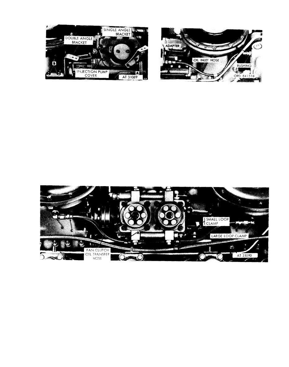
Figure 5-84. Removing or installing fuel injector tube angle brackets |
|
||
| ||||||||||
|
|
 --
Disconnect
1. Disconnect fuel injection pump oil inlet hose adapter
Remove
(A) in fuel injection pump adapter.
1. Remove two cap screws (A) attaching single angle
2. Disconnect inlet hose from pipe hushing (B) at
bracket to fuel injection pump. Remove bracket.
crankshaft damper and oil filter housing. Remove inlet
2. Remove two self-locking nuts (B) attaching double
hose.
angle bracket to front fan drive housing. Remove
Connect
bracket.
N o t e . The fuel injection pump oil inlet hose
Install
1. Position double angle bracket on front fan drive
has a swivel nut at only one end. This swivel end
housing. Install two self-locking nuts (B) securing
must be connected to the adapter (A).
bracket to housing.
1. Connect inlet hose to pipe bushing (B) at crankshaft
2. Position single angle bracket on fuel injection pump.
damper and oi[ filter housing.
Install two cap screws (A) securing bracket to pump.
2. Position inlet hose in engine with swivel nut end at
adapter (A) and connect hose to adapter.
injector tube angle brackets.
fuel injection pump oil inlet hose-engines
prior to rerouting of hose and clamps.
drive housing and remove and discard hose.
1. Remove assembled washer bolt (A) attaching small
4. Remove and discard elbows (D).
loop clamp to mounting base. Remove and discard
clamp.
Note. Pipe plugs will be installed in these
2. Disconnect fan clutch oil transfer hose at elbow (B) in
openings during r e b u i l d o f t h e f a n d r i v e
front fan drive housing.
3. Disconnect oil transfer hose at elbow (C) in rear fan
housings.
with transfer hose.
5-51
|
|
Privacy Statement - Press Release - Copyright Information. - Contact Us |
