 |
|||
|
|
|||
|
Page Title:
Figure 5-81. Removing or installing right turbo supercharger mounting base support. |
|
||
| ||||||||||
|
|
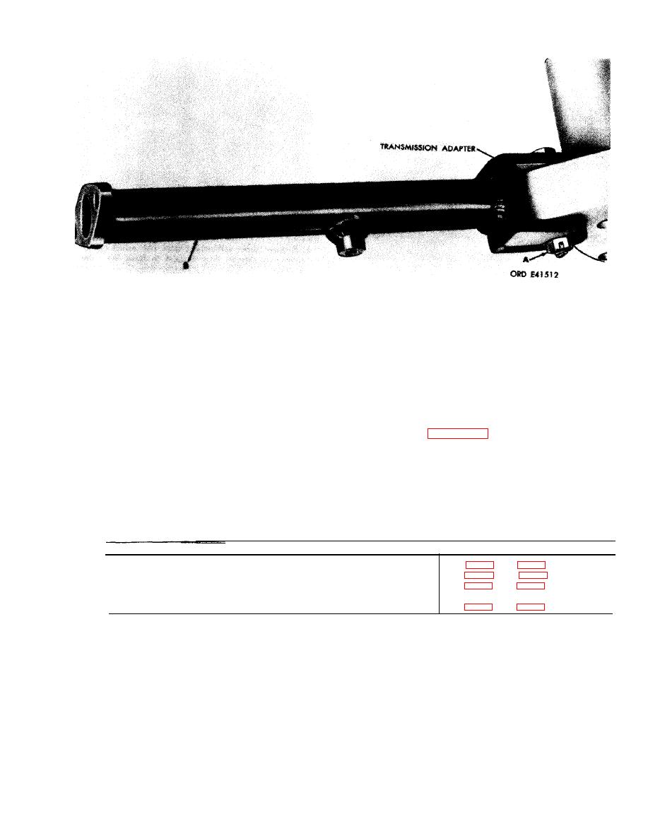 support is removed or installed in the same
Remove
1. Remove cotter pin, slotted nut (A), and bolt attaching
manner.
turbosupercharger mounting base support (B) to
Install
transmission adapter.
1. Position turbosupercharger mounting base support
2. Remove support.
(B) on transmission adapter.
2. Install bolt, slotted nut (A) and cotter pin securing
Note. Left turbosupercharger mounting base
support.
mounting base support.
R e f e r t o T a b l e 5 - 6 for illustrations and
5-9. Throttle Control Rods and Lever,
F u e l Injection P u m p O i l I n l e t H o s e ,
disassembly instructions. Figure references are
Turbosupercharger Oil Inlet Hose and
listed in the table.
Fire Extinguisher Tube, and Fuel ln-
jection Pump
Table 5-6. Throttle Control Rods and Lever, Fuel Injection Pump
Oil Inlet Hose, Turbosupercharger Oil Inlet Hose and
Fire Extinguisher Tube, and Fuel Injection Pump
Figure Reference
Component
Throttle Control Rods and Intermediate Throttle Lever
Fuel Injection Pump Oil Inlet Hose
Turbosupercharger Oil Inlet Hose and Fire Extinguisher
Tube
Fuel Injection Pump
5-49
|
|
Privacy Statement - Press Release - Copyright Information. - Contact Us |
