 |
|||
|
|
|||
|
Page Title:
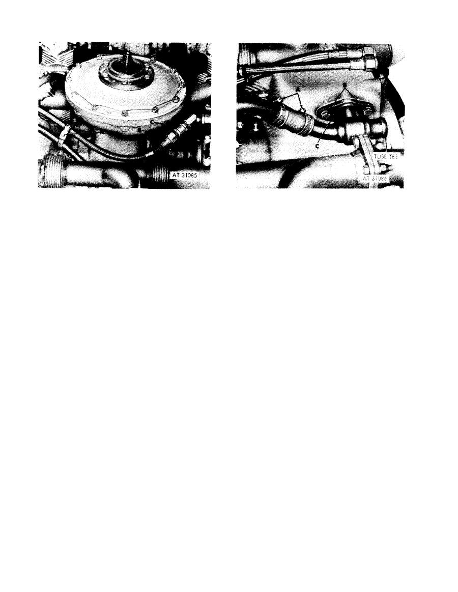
Figure 5-73. Removing or installing fuel return hose-engines with rerouted fuel return hose. |
|
||
| ||||||||||
|
|
 Remove
1. Remove pan head screw (A) and self-locking nut
Remove
attaching two cushioned clamps to fuel return hose and
1. Loosen two breather tube hose clamps (A).
turbosupercharger oil inlet hose.
2. Remove two bolts (B) and lock washers attaching
2. Disconnect fuel return hose (B) from fuel return check
crankcase breather tube tee to rear fan drive housing.
valve (C) and remove hose.
3. Remove tube tee. Remote and discard tube tee gasket
3. Remove fuel return check valve (C) from fuel in-
(C).
jection pump.
Install
Install
1. Position a new tube tee gasket (C) on rear fan drive
1. Install fuel return check valve (C) in fuel injection
housing. Position crankcase breather tube tee on
pump.
housing.
2. Install fuel return hose (B) and connect to fuel return
2. Install two bolts (B) and lock washers securing tube
check valve (C).
tee to drive housing.
3. Position one cushioned clamp on fuel return hose and
3. Tighten two breather tube hose clamps (A).
one cushioned clamp on turbosupercharger oil inlet
hose at position shown. Install pan head screw (A) and
Figure 5-74. Removing or installing
self-locking nut securing clamps.
crankcase breather tube tee-engines
Figure 5-73. Removing or installing fuel
with rerouted crankcase breather tube.
return hose-engines with rerouted
fuel return hose.
5-44
|
|
Privacy Statement - Press Release - Copyright Information. - Contact Us |
