 |
|||
|
|
|||
|
Page Title:
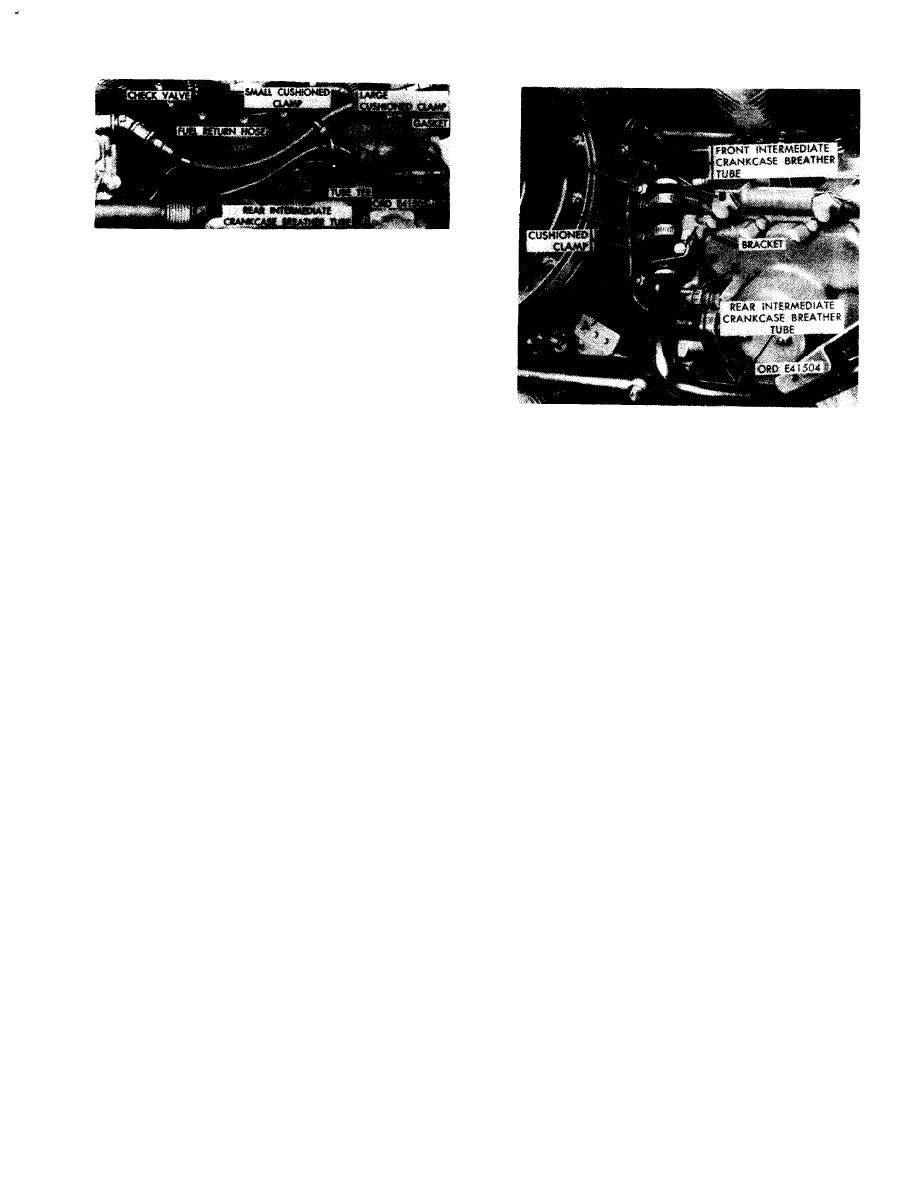
Figure 5-72. Disconnecting or connecting intermediate crankcase breather tubes at fuel injection pump clamp. |
|
||
| ||||||||||
|
|
 Remove
1. Remove self-locking nut and machine screw (A)
attaching large and small cushioned clamps from in-
termediate crankcase breather tube and fuel return
hose.
2. Disconnect fuel return hose (B) at check valve and
remove hose.
3. Loosen breather tube hose clamps (C).
4. Remove two bolts and lock washers (D) attaching
crankcase breather tube tee to rear fan drive and ac-
cessory drive housing. Remove tube tee and hose from
intermediate crankcase breather tube. Remove and
discard tube tee gasket.
Disconnect
5. Remove fuel check valve (E).
1. Remove three self-locking nuts and machine screws
Install
(A) attaching three small cushioned clamps on elec-
1. Install fuel check valve (E).
trical lead to three large cushioned clamps on in-
2. Install a new hose on tube tee. Connect tube tee to
termediate crankcase breather tube.
intermediate crankcase breather tube. Position new
2. Remove three large cushioned clamps (B) from front
gasket and install breather tube tee to rear fan and
and rear intermediate crankcase breather tubes and
accessory drive housing and secure with two bolts and
front intermediate crankcase breather tube.
lock washers (D).
3. Remove self-locking nut and bolt (C) securing
3. Tighten breather tube hose clamps (C).
breather tube clamp to bracket.
4. Position fuel return hose (B) and connect to check
4. Loosen two hose clamps (D) and remove rear in-
valve.
termediate crankcase breather tube. Remove cushioned
5. Position large and small cushioned clamp and install a
clamp and hose from tube.
machine screw and self-locking nut (A) securing large
5. Disconnect fuel injection pump electrical lead (E)
and small cushioned clamps at intermediate crankcase
from injection pump.
breather tube and fuel return hose.
Connect
1. Connect fuel injection pump electrical lead (E) to fuel
injection pump.
return hose and crankcase breather tube
2. Install cushioned clamp and hose on rear intermediate
crankcase breather tube and position tube. Tighten two
t e e - engines prior to rerouting
hose clamps (D).
of fuel return hose.
3. Install bolt and self-locking nut (C) securing breather
tube clamp to bracket.
4. Install one large cushioned clamp (B) on rear in-
termediate breather tube and two large cushioned
clamps (B) on front intermediate breather tube.
5. Install three machine screws and self-locking nuts (A)
securing three small cushioned clamps on the electrical
lead to the three large cushioned clamps on the crank-
case front and rear intermediate breather tubes.
Figure 5-72. Disconnecting or connecting
intermediate crankcase breather tubes at
fuel injection pump clamp.
5-43
|
|
Privacy Statement - Press Release - Copyright Information. - Contact Us |
