 |
|||
|
|
|||
|
Page Title:
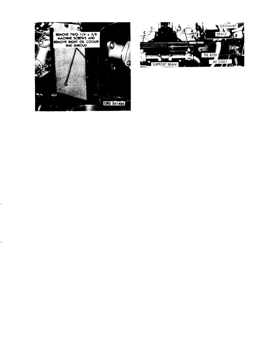
Figure 5-19. Removing or installing right oil cooler end shroud. |
|
||
| ||||||||||
|
|
 Remove
1. Remove self-locking nut (A), washer, and cap screw
attaching brace to support beam.
2. Remove self-locking nut (B), two spacers, bolt, and
grommet attaching brace to turbosupercharger tie rod.
3 . Remove six self-locking nuts (C) and three flat
w a s h e r s attaching support beam to cylinders and
rem ove beam.
Install
Figure 5-19. Removing or installing right oil
Note. The flat washers are located at cylinder
cooler end shroud.
Nos. 3, 4 and 5 on both cylinder banks.
1. Position support beam on engine and install six self-
locking nuts (C) and three flat washers securing beam
to cylinders.
2. Install self-locking nut (B), two spacers, bolt, and
grommet securing brace to turbosupercharger tie rod.
3. Install self-locking nut (A), washer, and cap screw
securing brace to support beam.
Figure 5-20. Removing or installing right oil
cooler support beam.
5-11
|
|
Privacy Statement - Press Release - Copyright Information. - Contact Us |
