 |
|||
|
|
|||
|
Page Title:
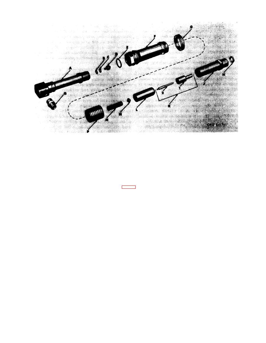
Figure 4-170. Disassembling or assembling fuel injector nozzle components. |
|
||
| ||||||||||
|
|
 correct gage pressure reading on the nozzle tester
Disassemble
1. Remove fuel injector nozzle assembly (K), with nozzle
may require various combinations of spacers
body (K-1) and nozzle valve (K-2) from valve stop
available in shim set -5365-235-1941. Although
spacer (L).
each nozzle assembly pressure reading may vary,
2. Remove valve stop spacer (L) and nozzle opening
e x p e r i e n c e will indicate the approximate spacer
pressure adjusting spring (N) with spring upper and
thickness or combination of spacer thickness
lower seats (D and M) from holder body (A). Do not
remove the spring adjusting upper and lower spacers ( B
required to make up pressure differences. The
and C) from spring upper seat (D) unless ajustment of
n o z z l e assembly must be completely assembled,
the nozzle opening pressure is necessary during testing
torque tightened and checked again on the
of the fuel injector nozzle and holder assembly ( para 4-
nozzle tester to assure proper spacer combination
17).
a n d pressure reading. This procedure may have
3. Remove and discard preformed packing (E) from
holder body (A).
t o be repeated several times before achieving a
4. Disassemble fuel injector nozzle assembly (K) by
s a t i s f a c t o r y reading.
removing nozzle body (K-1). It may be necessary to
1. Assemble nozzle valve (K-2) in nozzle body (K-1) to
soak the nozzle assembly in carbon removing solvent to
form fuel injector nozzle assembly.
aid in disassembly. It may be necessary to tap nozzle
2. Install a new preformed packing (E) in holder body
body downward on the edge of a wooden bench or other
(A).
similarly soft surface to remove valve.
3. Install spring upper seat (D), with spring adjusting
Note. The nozzle body and nozzle valve are
upper and lower spacers (D and M) in end of nozzle
f i t t e d individually during manufacture to form a
opening pressure adjusting spring (N). Install spring
lower seat (M) in opposite end of spring (N) and install
mated assembly. Individual parts are not in-
assembled spring and valve stop spacer (L) in holder
t e r c h a n g e a b l e . Therefore, extreme care must be
body (A).
taken during the cleaning, inspection, and repair
4. Install fuel injector nozzle assembly (K-1 and K-2) in
o p e r a t i o n s to keep these parts mated.
valve stop spacer (L).
Assemble
Note. During
assembly,
the
addition
or
removal of spring adjusting spacers to obtain the
Figure 4-170. Disassembling or assembling fuel injector nozzle components.
4-85
|
|
Privacy Statement - Press Release - Copyright Information. - Contact Us |
