 |
|||
|
|
|||
|
Page Title:
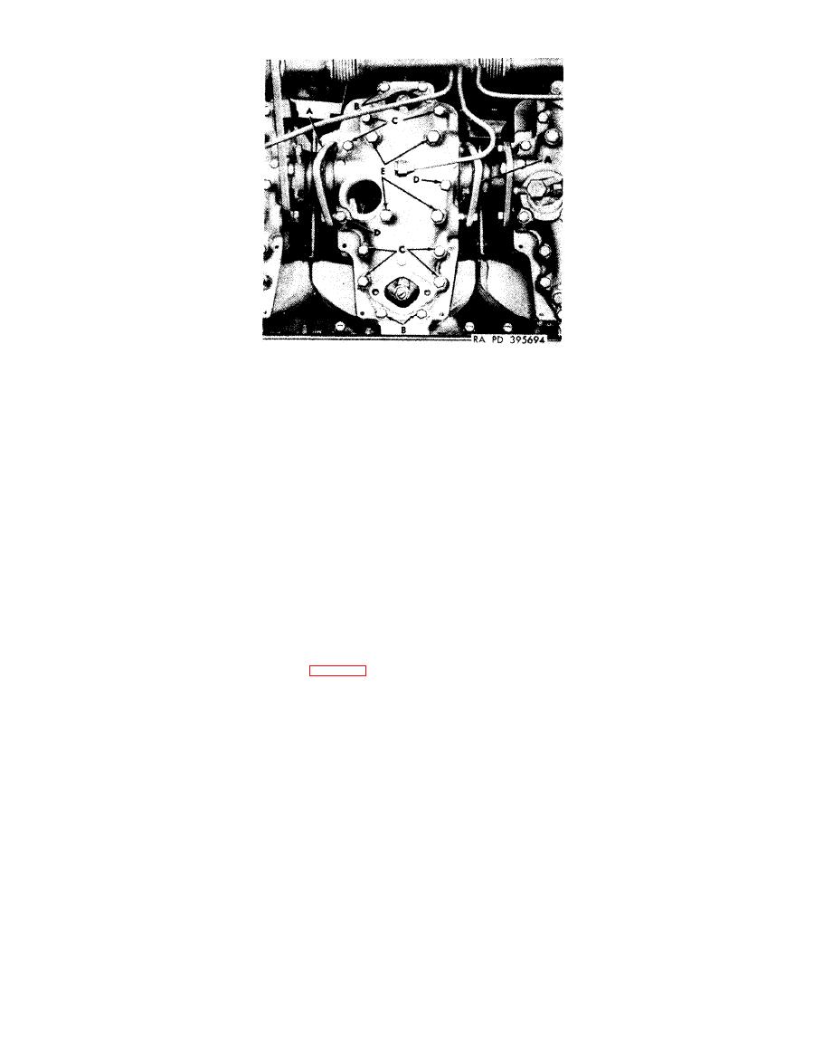
Figure 4-157. Removing or installing valve rocker arm cover bolts and removing valve rocker arm cover. |
|
||
| ||||||||||
|
|
 Remove
and valve stems, the rocker arm rollers are on the
camshaft base circle, and the valves are com-
Note. All valve rocker arm covers are removed
pletely closed.
in the same manner.
1. Separate intercylinder connector flanges (A) from
5. Remove four bolts (E) and packings with retainer and
valve rocker arm cover.
remove valve rocker arm cover.
Install
Note. Use a piece of shim stock to loosen
Note. The cylinder and valve rocker arm cover
flanges of intercylinder preformed hose.
are machined as an assembly. The number on
Caution; Do not damage sealing surface on
the rocker cover must be kept with its mating
flange of intercylinder preformed hose as it will
number on cylinder to insure camshaft bearing
cause oil leaks and replacement of hose will be
alinement
and
running
clearance.
required.
Note. The
bolts
and
screws
securing
valve
2. Remove four bolts (B) and flat washers.
rocker arm cover to cylinder must be torqued
3. Remove seven bolts (C) and flat washers.
4. Remove two screws (D) and flat washers.
carefully to prevent stripping of heli-coil inserts.
Note. Before removing rocker arm cover bolts
1. Position valve rocker arm cover on cylinder and install
(E),
instruction
5,
below,
the
tension
on
the
four bolts (E) and packings with retainer and tighten to
275-325 pounds inch torque.
valve rocker arms, caused by the valve springs.
2. Install two screws (D) and flat washers and tighten to
must be released. Turn engine, figure 4-51, until
100 pounds inch torque.
valve rocker arm rollers are on camshaft base
3. Install seven bolts (C) and flat washers and tighten to
circle, or until both valves are closed, to relieve
100 pounds-inch torque.
spring tension before removing cover. Check
4. Install four bolts (B) and flat washers and tighten to
100 pounds inch torque.
rocker arms to see that they move up and down.
5. Position intercylinder connector flanges (A) on valve
If movement (clearance) cannot be felt, turn
rocker arm cover.
engine until clearance is evident. When clearance
is obtained between both adjusting screw pads
rocker arm cover bolts and removing valve
rocker arm cover.
4-77
|
|
Privacy Statement - Press Release - Copyright Information. - Contact Us |
