 |
|||
|
|
|||
|
Page Title:
Figure 4-154. Removing or installing cylinder head shroud plate. |
|
||
| ||||||||||
|
|
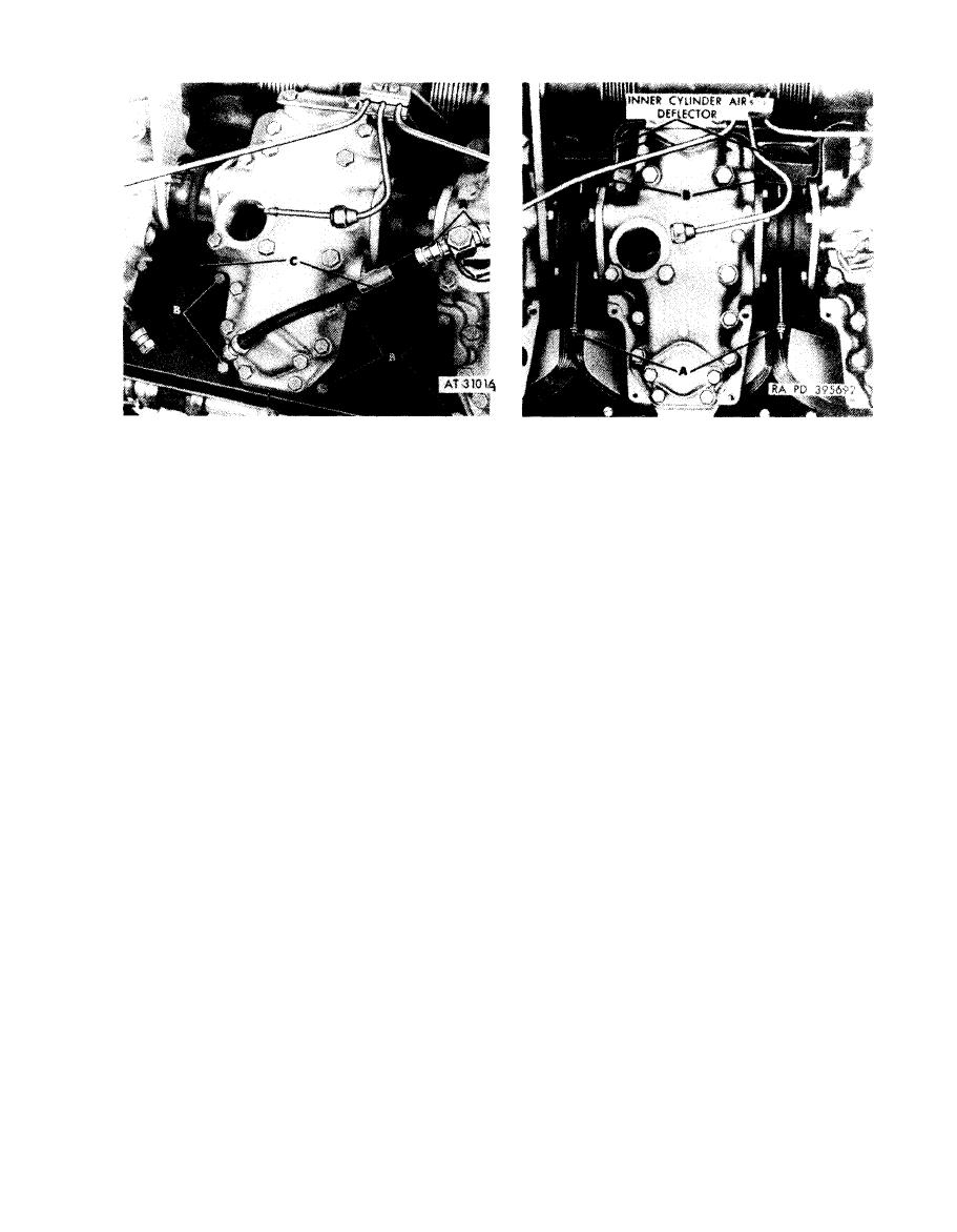 Remove
Disconnect
1. Remove fuel injector nozzle fuel return hose (A).
1. Remove self-locking nuts (A) from hooks attaching
2 . Remove four screws (B) and external tooth lock
inner cylinder air deflectors.
washers attaching each cylinder head shroud plate.
2. Lift air deflector (B) from cylinder fins and rocker
3. Remove two cylinder head plates (C).
arm covers. It is not necessary to remove deflectors.
Install
Connect
1. Position each cylinder head shroud plate (C) between
1. Position inner cylinder air deflectors (B) between
cylinders.
cylinder fins and rocker arm covers
2 . Install four screws (B) and external tooth lock
2 . Install self-locking nuts (A) on hooks securing
washers securing each plate.
deflectors.
3. Install fuel injector nozzle fuel return hose (A).
Figure 4-155. Disconnecting or connecting
Figure 4-154. Removing or installing
inner cylinder air deflector.
cylinder head shroud plate.
4-75
|
|
Privacy Statement - Press Release - Copyright Information. - Contact Us |
