 |
|||
|
|
|||
|
Page Title:
Figure 4-117. Removing or installing intake manifold assembly-left side. |
|
||
| ||||||||||
|
|
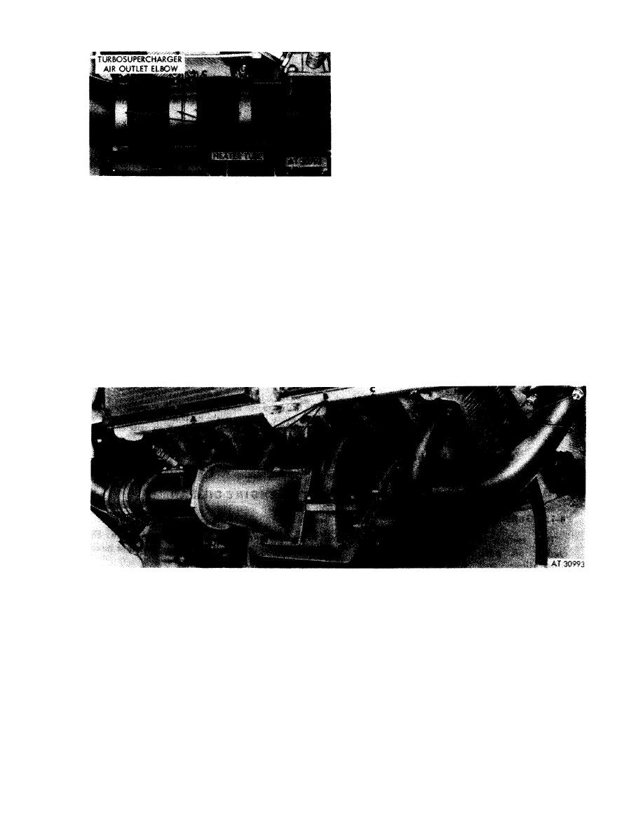 Disconnect
1. Loosen four hose clamps (A).
2. Separate hoses (B), sliding one hose on the heater tube
and the other hose on the turbosupercharger air outlet
elbow.
3. Remove turbosupercharger outlet elbow tube sleeve
(C).
Connect
1. Position turbosupercharger outlet elbow tube sleeve
(C) between elbow tube and heater tube.
2. Slide one hose (B) from elbow tube on sleeve (C).
Slide second hose (B) from heater tube on sleeve (C).
3. Tighten four hose clamps (A).
Figure 4-116. Disconnecting or connecting
turbosupercharger air outlet elbow and
heater tube.
Install
Remove
1 . Remove 12 nuts (A) and lock washers attaching
1. Install six new intake manifold gaskets (C).
2. Position manifold assembly on cylinder studs. Install
intake manifold tubes to cylinders 1L, 2L, 5L, and 6L.
six nuts (B), lock washers, and flat washers securing
2. Remove six nuts (B), lock washers, and flat washers
intake manifold tubes to cylinders 3L and 4L.
attaching intake manifold tubes to cylinders 3L and 4L.
Remove manifold assembly.
3. Install 12 nuts (A) and lock washers securing intake
manifold tubes to cylinders 1L, 2L, 5L, and 6L.
3. Remove and discard six intake manifold gaskets (C).
Figure 4-117. Removing or installing intake manifold assembly-left side.
4-57
|
|
Privacy Statement - Press Release - Copyright Information. - Contact Us |
