 |
|||
|
|
|||
|
Page Title:
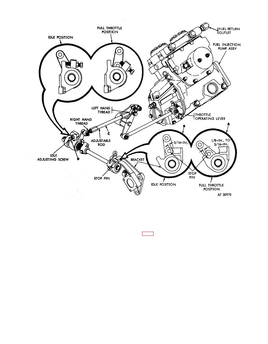
Figure 4-85. Throttle linkage adjustment-schematic diagram |
|
||
| ||||||||||
|
|
 5. Check the fuel supply as follows:
1. With throttle linkage in full throttle position (A),
a. Connect the necessary fuel and oil hoses and
clearance between lever stop pin and stop on bracket
e l e c t r i c a l harnesses to the engine to permit slave
must be 1/8 to 3 / 16 inch.
operation from the vehicle to check for fuel and / or oil
2. With throttle linkage in idle position (B), clearance
leaks. Activate the vehicle in-tank fuel pumps to make
between lever stop pin and stop on bracket must be
certain fuel is supplied to and through the fuel injection
3 / 16 inch.
pump. Fuel should flow from the fuel return outlet (fig.
3. When the foregoing clearances are not met, loosen
l o c k nuts on adjustable rod (C) and adjust rod as
b. Crank the engine with the starter until fuel flows
necessary to obtain required clearance. Tighten lock
f r o m all outlet ports in the fuel injection pump
nuts after adjustment.
hydraulic head.
4. The idle adjusting screw (D) must not be set until
engine is installed and tested.
Figure 4-85. Throttle
linkage
adjustment-schematic
diagram.
4-42
|
|
Privacy Statement - Press Release - Copyright Information. - Contact Us |
