 |
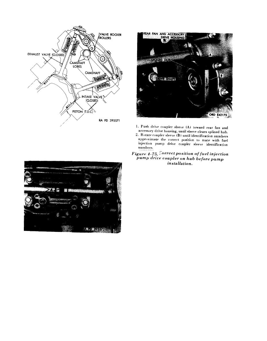
|||
|
|
|||
|
Page Title:
Figure 4-73. Position of camshaft lobes for injection pump timing. |
|
||
| ||||||||||
|
|
 Note.
Camshaft lobes must be in position
Shown for proper injection pump timing.
Figure 4-73. Position of camshaft lobes for
injection pump timing.
1. Check length of bolts (A) securing fuel injection pump
mounting base to crankcase. Discard bolts that are 1-
7 / 32 in. long and replace with the correct 1-3 / 8 in.
long bolts (5305-725-0154) and lock washers (5310-
584-5272). Torque tighten bolts to 720 to 780 pounds-
inch.
2 . Position new preformed packing (B) on mounting
base oil transfer tube.
Figure 4-74. Installing preformed packing
on fuel injection pump mounting base oil
transfer
tube.
4-38
|
|
Privacy Statement - Press Release - Copyright Information. - Contact Us |
