 |
|||
|
|
|||
|
Page Title:
Figure 4-49. Removing or installing angle bracket from fuel injection pump |
|
||
| ||||||||||
|
|
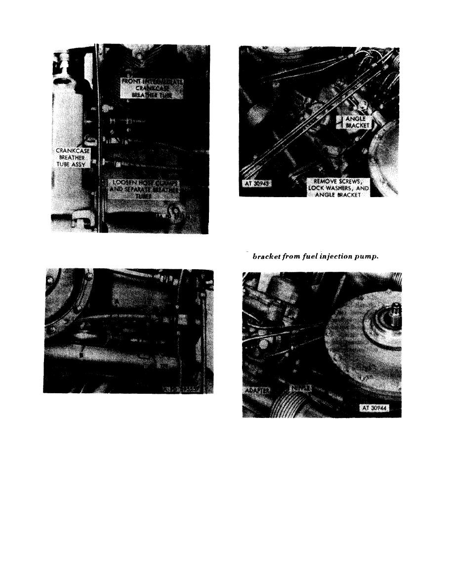 Note. Screws
and
lock
washers
are
part
of
injection
pump
assembly
and must be re-
installed
after
the angle
bracket has been
removed.
Figure
4-47.
Disconnecting
or
connecting
crankcase breather tube at front of engine.
Disconnect
1. Loosen hose clamps (A) and separate rear in-
termediate crankcase breather tube (B) from breather
tube tee.
Disconnect
2. Move breather tube (B) aside so fuel injection angle
1. Disconnect fuel inlet hose (A) from adapter.
bracket can be removed.
2. Disconnect oil inlet hose (B) from nipple.
Connect
Connect
1. Connect rear intermediate crankcase breather tube
1. Connect oil inlet hose (B) to nipple.
(B) to breather tube tee.
2. Connect fuel inlet hose (A) to adapter.
2. Tighten hose clamps (A).
Figure 4-48. Disconnecting or connecting rear
4-50.
Disconnecting
or
connecting
intermediate crankcase breather tube at tube
fuel injection pump oil and fuel inlet hoses.
tee-engines prior to relocated crankcase
breather tube.
4-26
|
|
Privacy Statement - Press Release - Copyright Information. - Contact Us |
