 |
|||
|
|
|||
|
Page Title:
Figure 4-15. Removing or installing generator and boot |
|
||
| ||||||||||
|
|
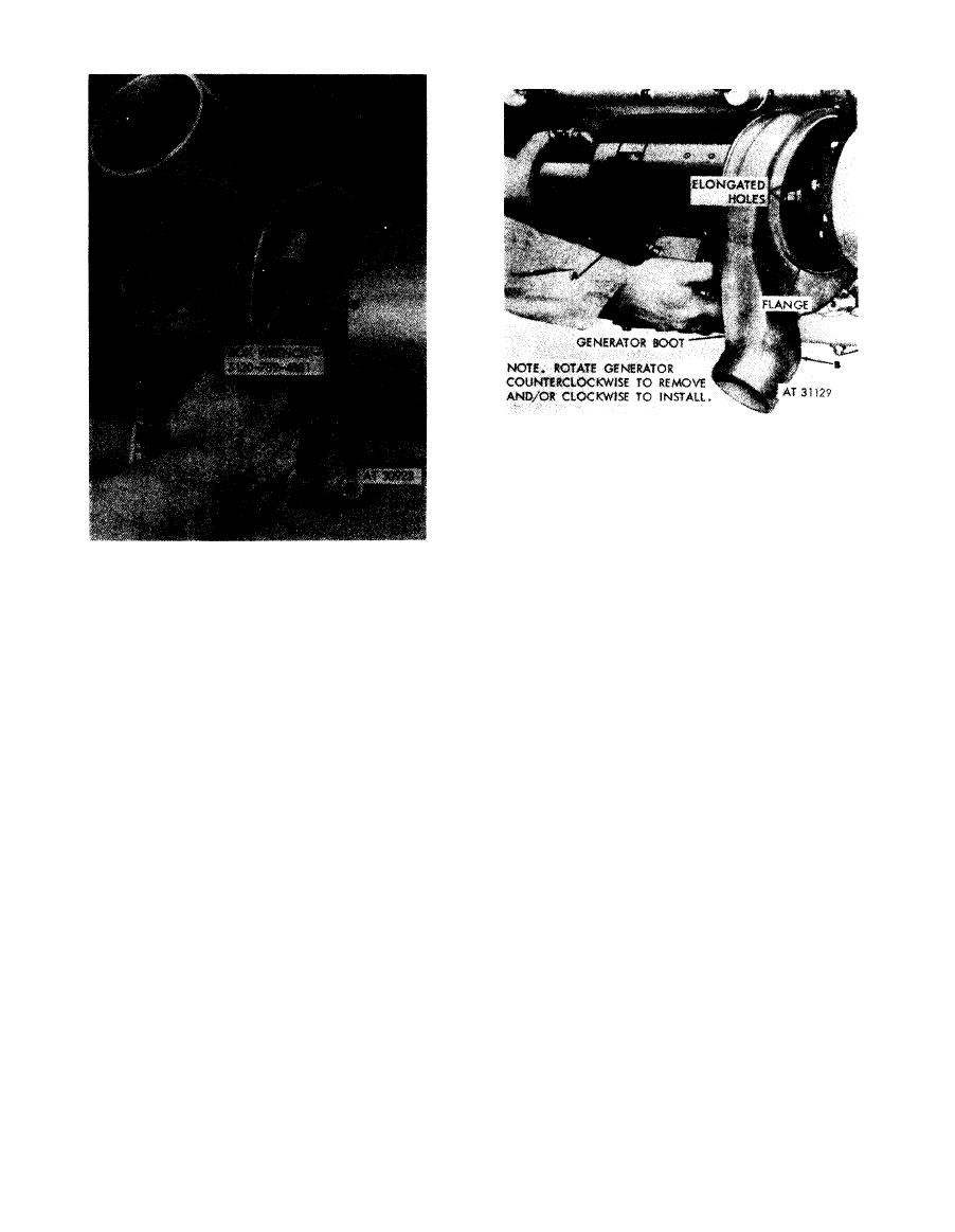 Remove
1 . Rotate generator (A) counterclockwise until large
elongated openings in flange are alined with mounting
nuts, and remove generator and boot.
2. Remove boot (B) from generator.
Install
1. Position boot (B) on generator.
2. Position generator (A) so that large elongated
openings in flange are alined with mounting nuts, and
Loosen
install generator and boot.
1. Slide boot back on generator far enough to expose the
mounting nut access openings (A).
Figure
4-15.
Removing
or
installing
2. Loosen, but do not remove, six self-locking nuts (B),
generator
and
boot.
using box wrench -5120-789-4881 to permit rotation of
generator to align the large openings in the elongated
mounting slots.
Note. In cases where boot is rigid, it may be
necessary to slide one side of boot back and
loosen
three
mounting
nuts,
then
repeat
the
procedure for the other three nuts. Do not cut or
otherwise mutilate boot.
Tighten
1. Position boot on generator just far enough so that the
mounting nut access openings (A) are exposed.
2. Tighten six self-locking nuts (B) using box wrench-
5120-789-4881.
Figure
4-14.
Loosening
or
tightening
generator
mounting
nuts
using
box
wrench-5120-789-4881.
4-8
|
|
Privacy Statement - Press Release - Copyright Information. - Contact Us |
