 |
|||
|
|
|||
|
Page Title:
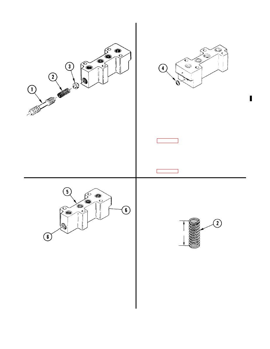
REMOVE DIRECTIONAL CONTROL SLIDE |
|
||
| ||||||||||
|
|
 TM 9-2520-270-34
4.
U S I N G RETAINING-RING PLIERS,
R E M O V E AND DISCARD RETAINING
RING (4).
5.
C L E A N SECOND RANGE RELAY
VALVE ASSEMBLY.
CAUTION
Second range directional control slide and
a. Clean housing and piece parts. See
slide bore in valve are precision fit parts.
Do not drop, scratch, or nick slide. Equipment
can be damaged.
6.
I N S P E C T SECOND RANGE RELAY
VALVE ASSEMBLY.
3. REMOVE DIRECTIONAL CONTROL
a. Inspect housing and piece parts. See
SLIDE (1), SPRING (2), AND
RETAINER (3).
7 . CHECK HOUSING (5).
a. Using small
hole gage set and
caliper set, measure
diameter of
bore (6) in both ends
of housing
(5). Do not measure
threads.
8 . CHECK SPRING (2).
b. If either measurement is more than
a. Using
indicator caliper, measure free
0.5009 inch (12.723 mm), replace valve
length
of spring (2), Replace spring
assembly and go to END OF TASK.
if free
length is less than 0.90 inch
If not, go to step 8.
(22.86
mm).
4-522
Change 1
|
|
Privacy Statement - Press Release - Copyright Information. - Contact Us |
