 |
|||
|
|
|||
|
|
|||
| ||||||||||
|
|
 TM 9-2520-270-34
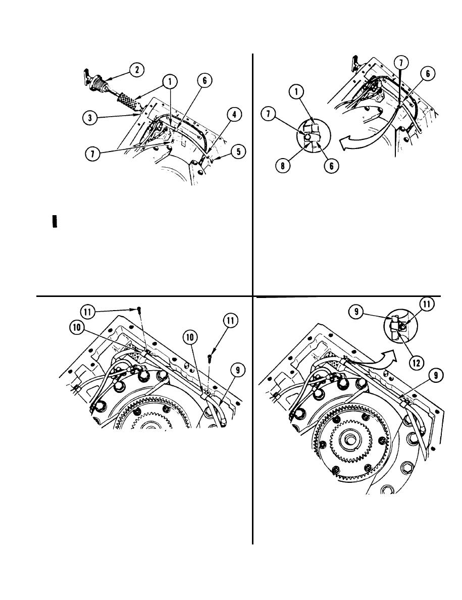
44. USING 3/8-lNCH DRIVE TORQUE
WRENCH WITH EXTENSION, AND
43. INSTALL DIPSTICK TUBE
7/16-lNCH SOCKET, TORQUE
ASSEMBLY (1) AND DIPSTICK (2).
SCREW (7) TO 110-120 in-lb
a. Feed dipstick tube assembly (1)
(127-138 cmkg).
through hole (3). Place lower end (4)
of dipstick tube in hole (5).
45. INSTALL NEW LOCKWIRE (8).
b. Install dipstick (2)
a. Using wire-twister pliers, install
Iockwire (8) through screw (7) and
c. Position flat side of clamp (6)
around dipstick tube assembly (1)
away from main housing and install
and clamp (6).
screw (7).
46. SECURE HOSE ASSEMBLY (9).
a. Position two clamps (10).
b. Using 3/8-inch drive ratchet handle
and 5/32-inch socket wrench attach-
ment, install two new screws (11).
47. USING 3/8-lNCH DRIVE TORQUE
48. INSTALL TWO NEW LOCKWIRES (12).
WRENCH WITH EXTENSION AND
a. Using wire-twister pliers, install lock-
5/32-lNCH SOCKET WRENCH ATTACH-
wires (12) through two screws (11)
MENT, TORQUE TWO SCREWS (11)
and around hose assembly (9).
TO 35-45 in-lb (40-52 cmkg).
GO TO NEXT PAGE
4-439
Change 1
|
|
Privacy Statement - Press Release - Copyright Information. - Contact Us |
