 |
|||
|
|
|||
|
|
|||
| ||||||||||
|
|
 TM 9-2520-270-34
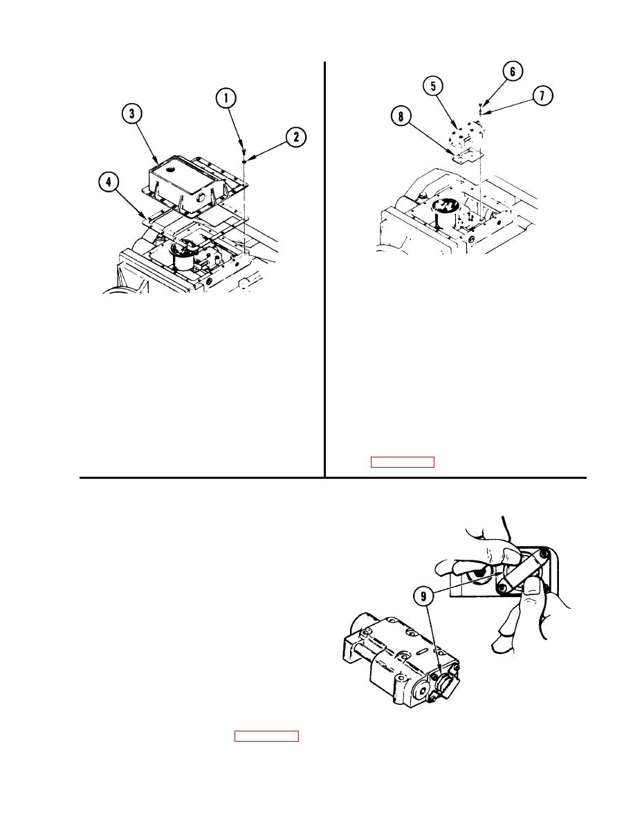
5 . REMOVE COOLANT AND TIME DELAY
VALVE ASSEMBLY (5).
a. Remove six screws (6) and
washers (7).
b. Using plastic-faced hammer, tap
and remove valve assembly (5).
REMOVE 17 BOLTS (1).
3.
c. Remove and discard gasket (8).
a. Remove 17 bolts (1) and lock
6 . INSPECT INSERTS IN BOTTOM
washers (2). Discard lock washers.
OF MAIN HOUSING.
4.
REMOVE SUMP COVER (3).
a. Repair inserts if damaged. See task
REPAIR MAIN HOUSING INSERTS,
a. Remove cover (3) and gasket (4).
Discard gasket.
7.
I N S P E C T DIRECTIONAL CONTROL
SLIDE (9) FOR FREE MOVEMENT.
a. Push in slide (9) and release.
Slide must snap back.
b. If slide (9) is stuck in housing,
go to step 8. If not, go to step 9.
R E P A I R COOLANT AND TIME
8.
DELAY VALVE ASSEMBLY, page 4-408.
GO TO NEXT PAGE
4-405
|
|
Privacy Statement - Press Release - Copyright Information. - Contact Us |
