 |
|||
|
|
|||
|
Page Title:
CHECK ALINEMENT OF SHOULDERED SHAFT POINTER |
|
||
| ||||||||||
|
|
 TM 9-2520-270-34
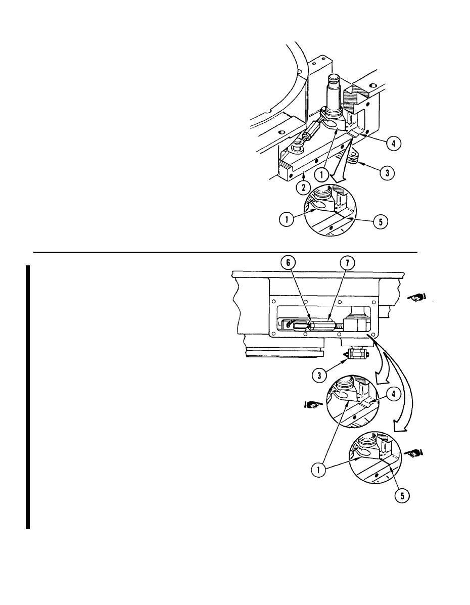
NOTE
Two different alinement indicators are used
in the output assemblies.
17. CHECK ALINEMENT OF SHOULDERED
SHAFT POINTER (1).
a.
Repairer and helper turn left-hand
output housing (2) over.
Rotate lever arm (3) and apply firm
b.
pressure.
c.
Check that pointer (1) alines with
v-groove indicator (4) or scribe mark
indicator (5).
d.
If Pointer (1) does not aline with
indicator (4) or (5), go to step 18.
If pointer does aline with indicator, go
to step 19.
NOTE
Two different alinement indicators are used
in the output assemblies.
This procedure contains only a coarse pointer
adjustment. The fine pointer adjustment is done
in the vehicle.
18. ADJUST POINTER (1).
a.
Release lever arm (3). Loosen
jam nut (6).
b.
Adjust pointer (1) by rotating adjuster
nut (7). Tighten jam nut (6).
c
Rotate lever arm (3) and apply firm
pressure.
d.
Check that pointer (1) alines with
v-groove indicator (4) or scribe mark
indicator (5).
e.
If pointer (1) does aline, go to step 18.1.
If after repeated adjustments pointer (1)
will not aline, go to step 20.
1 8 . 1 USING 1/2-lNCH DRIVE TORQUE
WRENCH WITH ADAPTER AND
9 / 1 6 - l N C H CROWFOOT, TORQUE
NUT (6) TO 17-20 ft-lb (2-3 mkg).
Change 1
4-318
|
|
Privacy Statement - Press Release - Copyright Information. - Contact Us |
