 |
|||
|
|
|||
|
|
|||
| ||||||||||
|
|
 TM 9-2520-270-34
NOTE
Spur gear and bearing may have been removed.
Keep it with this housing.
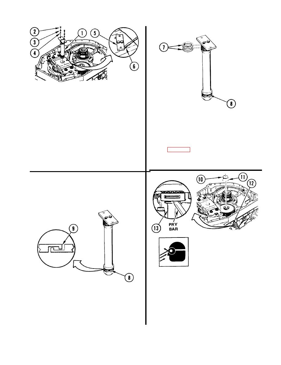
3. REMOVE SPINDLE ASSEMBLY (1)
IF INSTALLED.
4 . REMOVE AND DISCARD TWO
Remove two screws (2), washers (3),
a.
PREFORMED PACKINGS (7).
and sleeve spacers (4).
5. INSPECT METAL SEAL RING (8).
Rotate spindle cap (5) until it
b.
partly covers screw hole (6).
a. Inspect ring (8) for damage. See
Using screwdriver in screw holes (6),
c.
pry up spindle cap (5).
b. If ring (8) is damaged, go to step 6.
If not, go to step 7.
Remove spindle assembly (1).
d.
WARNING
Use care when removing
retaining ring. Retaining ring
can fly. Personnel can be
injured. Always wear goggles.
7. REMOVE RETAINING RING (10) AND
SHIM (11).
a. (H) Reach in through controller
opening (12) and pry up cross
6. REMOVE RING (8).
shaft (13).
a.
Squeeze ring (8) with fingers until
b. Using retaining-ring pliers, remove
hooks (9) release.
retaining ring (10).
Spread open and remove ring (8).
b.
c. Remove shim (11).
Discard ring.
GO TO NEXT PAGE
4-221
|
|
Privacy Statement - Press Release - Copyright Information. - Contact Us |
