 |
|||
|
|
|||
|
|
|||
| ||||||||||
|
|
 TM 9-2520-270-34
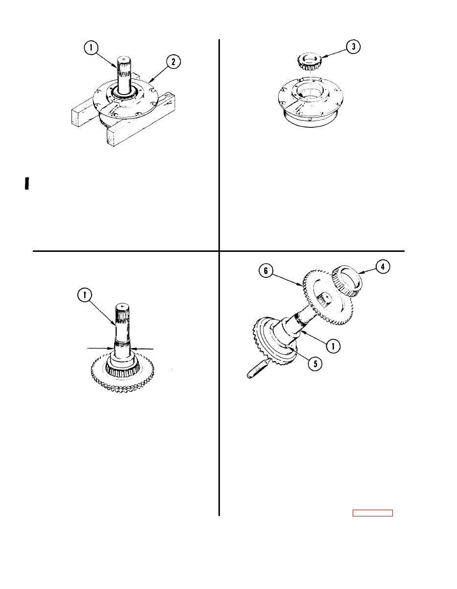
7. REMOVE CONE AND ROLLERS (3).
NOTE
6.
REMOVE BEVEL GEAR SHAFT (1).
If either cone or rollers is damaged, both
a. Place housing assembly (2) on
must be discarded.
two wood blocks (Item 6).
8. INSPECT CONE AND ROLLERS (3).
b. Using plastic-faced hammer, tap
a. Inspect cone and rollers (3) for
bevel gear shaft (1) from housing
damage. See TM 9-214.
assembly (2).
b. Discard cone and rollers (3) if
c. Place housing assembly (2) on
damaged.
workbench.
10.
REMOVE CONE AND ROLLERS (4).
a. Insert drift punch through holes (5)
in gear shaft (1) and tap off cone
and rollers (4),
NOTE
b. Discard cone and rollers (4).
If gear shaft is worn, bevel gear and pinion
must be replaced as a matched set.
REMOVE SPUR GEAR (6).
11.
9. CHECK BEVEL GEAR SHAFT (1).
a. Using arbor press, remove gear (6).
a. Using micrometer caliper set,
measure outside diameter of shaft (1).
DISCARD BEVEL GEAR SHAFT (1).
12.
b. If measurement of shaft (1) is less
13.
REPLACE PINION. See task REPLACE
than 2.2500 inches (57.150 mm),
INPUT BEVEL ASSEMBLY, page 4-94.
go to step 10. If not, go to step 16.
Change 1
4-128
|
|
Privacy Statement - Press Release - Copyright Information. - Contact Us |
