 |
|||
|
|
|||
|
|
|||
| ||||||||||
|
|
 TM 9-2520-270-34
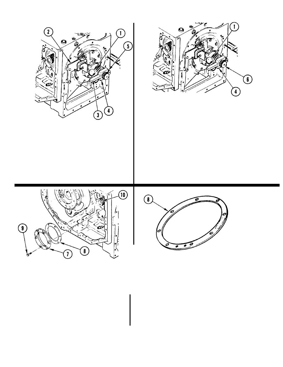
95. C H E C K BACKLASH.
a. Turn input gearshaft (6) left.
b. Zero dial indicator (1).
c. Turn gearshaft (6) right, by hand,
enough to read backlash on
94. INSTALL DIAL INDICATC)R (1).
indicator (1).
a. Position dial indicator (1) on
bracket (2) with C-clamp.
96. REMOVE TWO C-CLAMPS, DIAL
b. Aline dial indicator (1) with actuator
I N D I C A T O R (1), AND ACTUATOR (4),
indicator line (3) on actuator (4).
97. IF BACKLASH
IS NOT 0.008-0.011 INCH
c. Turn actuator (4) to actuate
(0.20-0.28 mm),
GO TO STEP 98. IF
indicator (1).
BACKLASH IS
0.008-0.011 INCH
d. Tighten actuator screw (5).
(0.20-0.28 mm),
GO TO STEP 114.
98. REMOVE RETAINER (7) AND
NOTE
SHIM(S) (8).
Thickness of each shim is marked on face of shim.
a.
Working on left side of transmission,
remove six bolts (9).
99. FIND TOTAL THICKNESS OF ALL
SHIM(S) (8).
b.
Using plastic-faced hammer, tap spur
I
gearshaft (10) from opposite side of
100. IF BACKLASH IS GREATER THAN
transmission to loosen retainer (7).
0.011 inch (0.28 mm), GO TO
c.
Using pry bar behind shim(s) (8),
STEP 101. IF BACKLASH IS LESS THAN
carefully remove retainer (7) and
0,008 INCH (0.20 mm), GO TO
shim (s).
STEP 102.
4-114
|
|
Privacy Statement - Press Release - Copyright Information. - Contact Us |
